
 |
| RECEIVER ROBOT |
Now I am going to tell you how to make a computer controlled wireless robot using 8051 microcontroller. Computer's can talk to microcontroller's via serial communication but in the present scenario serial port's are not available in the laptop so we can use a USB2SERIAL converter. In a very simple manner we are going to communicate the controller with computer via serial communication so that we can send the serial data from our computer keyboard. Once we get the computer keyboard data on the microcontroller we will be able to write a program to control anything by a computer whether it is robot or device.
Our robot is divided into two parts: Transmitter Module, Receiver Module
TRANSMITTER MODULE: The transmitter part of this project is use to transmit the 4bit data which cause to run the motor on the receiving end. We use the computer to send the command's to the controller via serial transmission. The microcontroller will make decision based on that data and generate a 4bit data which is further encoded by the encoder and transmit over an RF channel through an RF module. Here is a block diagram of the transmitter module:
| Transmitter |
As we can see into the Transmitter block diagram this transmitter divided further into 6 part's:
> Power Supply
> Computer
> Level shifter(max232)
> Microcontroller
> Encoder(HT12E)
> RF Module
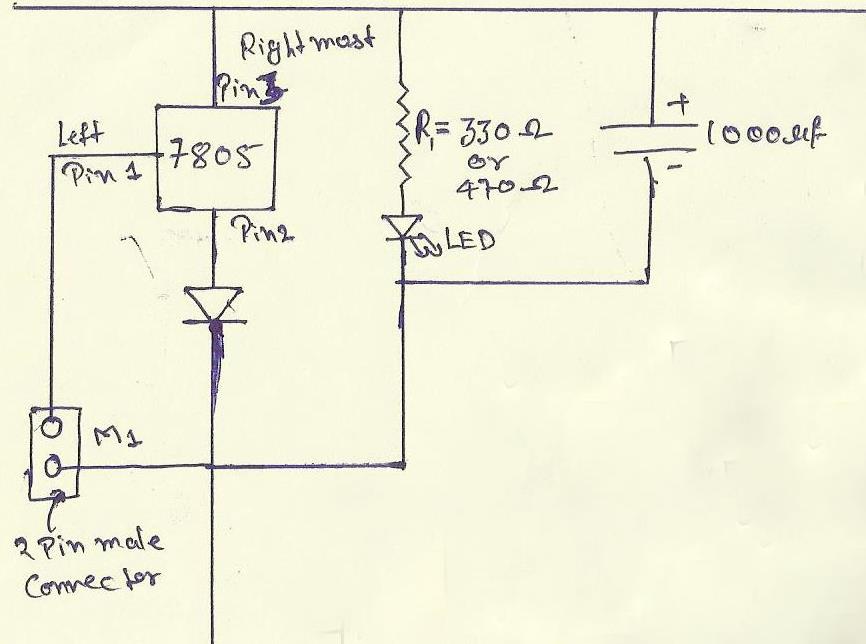
POWER SUPPLY: Before making any circuit we need to design its power supply it consist of many part like step down, ac-dc conversion, voltage stabilizing etc but we will giving the power to our board from an 12-volt adapter so our power supply consist of a voltage regulator,capacitor,diode, led and connector.
 |
| Power Supply |
 |
| Voltage regulator |
- 7805:-It is the voltage regulator ic as pin diagram is shown.
- diode IN4007 and the silver line part is its negative.
- resistor R1=330ohm or we can also use 470ohm because it is use with the led.
- A 2 pin male connector is required for giving the power to the circuit the +ve will connect with 1 pin of 7805.
- A 1000uf capacitor is also use with power supply to reducing the ripple or maintaining the continuity.
- Led:-the cutted portion of the led is negative.
 |
| hyper terminal window |
COMPUTER: Here the computer is use to send the command to the microcontroller via serial communication for this purpose we use the usb2serial cable to connect the computer to my circuit. Because in present their is no serial port into the computer's. Now for connecting my computer to the serial port we use an application named HYPER TERMINAL so tht we can send the data and also see what exactly we are sending to the microcontroller and we can also see what the microcontroller do after getting the signal from computer.
By this hyperterminal we send the ASCII codes and by those command's we easily make the decision those decision will be further use.
DB9 CONNECTOR: DB9 connector is use to connect the computer with your programmer board it uses the RS232 cable to connect the DB9 port has 9 pins each pin has its own function but we will use only pin no 2 , 3 and 5.

- pin no 2 is known as recieved data bit when controller transmit the data bit then computer recive from this pin. This is connected to the 14th pin of max232.
- pin no 3 is named as transmit data the data will transmit form the computer with the help of this pin and this is connected 13th pin of max232.
- pin no 5 we make this pin normally ground.
LEVELSHIFTER: The MAX232 is an Integrated Circuit that convert signal from an RS232 serial port to signal suitable for use in ttl compaitable digital logic circuits.The MAX232 is a dual driver/receiver and typically converts the RX, TX, CTS and RTS signals.For more details of MAX232 you can download the datasheet of it form here. download

- here the values of all the capacitors are 0.1 uf.
- 16 pin is vcc should be maintained at 5volt dc.
- the 15th pin becomes ground.
- T1out-pin is use to send the data serially to the computer.
- R1in-pin is use to recieve the data from the computer serially.
- T1in-pin is use to tramsmitt the data from microcontroller to MAX232 which is actually going to computer.
- R1out-pin is use for send the incoming data from MAX232 to microcontroller which is actually come from computer.
- Download the MAX232 datasheet here.download
MICROCONTROLLER: The processing is the most important part of the robot. Till now we get the data from the computer now based on that data we have to make some decision so here the role of microcontroller is coming up. We use an 8051 microcontroller for our circuit to give them a decision capability. Our microcontroller is made up by nxp the product name is P89V51RD2
The basic circuit to initialize the microcontroller is shown below. We just need an reset circuit and oscillator to run the program.
As we can see in above block diagram the Receiver module can further divided into 5 parts:
now You can make your own computer controlled robot easily.
C PROGRAM OF COMPUTER CONTROLLED ROBOT:
//Program to interface computer with 8051 microcontroller (8051 architecture)
#include<reg51.h>
unsigned char rcv_data;
void receive() //Function to recieve data serialy from RS232
{
while(RI==0);
rcv_data = SBUF;
RI=0;
}
void compare()
{
if(rcv_data=='w') // forward
P2=0x0a;
else if(rcv_data=='a') // left
P2=0x08;
else if(rcv_data=='s') // right
P2=0x05;
else if(rcv_data=='d') // backward
P2=0x02;
else
P2=0x00;
}
For program of this robot click here
************************* VIDEO OF COMPUTER CONTROLLED ROBOT****************
The basic circuit to initialize the microcontroller is shown below. We just need an reset circuit and oscillator to run the program.
 |
| 8051 micro controller circuit |
we use serial port as an input port and port 2 as an output port.
so the Data from the computer will connect pin 11(rx) 12(tx) of the microcontroller and motor should be connect with pin 21,22,23,24.
For forward the data to the serial port is 'w' or for backward it is 's' then for left its 'a' and for right it is 'd'.
Here is the full circuit diagram of this robot transmitter module with each component...
RECEIVER MODULE: Now at the Receiver side firstly we have RF receiver module which get the encoded data on it and convert that data into the voltage signal and that data is then applied to the decoder IC(HT12D) which decoded it into the 4bit data which is further apply on the motor driver IC(L293D) basically a h-bridge to provide the high current to the motor. And finally the motor will operate as the user want who's sitting on the computer.
Encoder(HT12E IC):- The HT12E is an 4bit encoder which encode the input data applied on it .The pin description of the HT12E is shown in the figure .
 |
| Encoder |
- pin (1 to 8) A0-A7 known as address bits so we do not need to consider them.
- pin no (9 and 18) are use to bias the IC as pin-18 as VCC and pin-9 as GND.
- pin - 17 is connected to the rf transmitter module Din.
- pin-16 and pin-15 are connected by an Osc resistor known as Roscc(1.1 Mohm)
- pin-14 is connected to ground to enable the transmitt.
- pin-13 to pin-10 are known as AD0 to AD3 those having the 4bit data which is required to transmit.
RF Transmitter Module(TX):- The transmitter module is working on the frequency of 433MHz and is easily available in the market at the cost of 250rs .
 |
| RF Transmitter module |
- The vcc pin is connected to the +terminal in the circuit.
- The data pin is connected to the HT12E(pin no-17) that is transmitted or we can say that encoded data.
- The next pin is shown in figure is GND that is connected to the ground terminal.
- Now the last pin ANT this is connected to a small wire as an antenna.
Here is the full circuit diagram of this robot transmitter module with each component...
 |
| FULL TRANSMITTER CKT |
Now the modules of a Receiver module can be shown in the block diagram:
 |
| Receiver Module |
> Power Supply
> RF Receiver
> Decoder(HT12D)
> Motor driver(L293D)
> Motor's(100 rpm)
POWER SUPPLY: The power supply will be same as discussed above:.
RF RECEIVER MODULE: The RF receiver module will receive the data which is transfered by the Transmitter module. It is also working as similar to the transmitter module-
- Connect the +vcc pin to the 5volt terminal
- Connect the ground pin to the ground terminal
- The data pin is then connected to the HT12D (pin-14)
- So that we can get the decoded 4 bit data

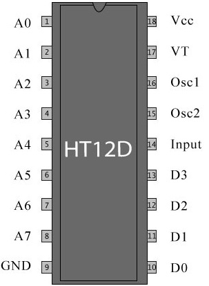
DEECODER(HT12D): In very simple way we can say that an HT12D converts that serial data into parallel which is received by the rf receiver module.The input data is decoded when no error or unmatched codes are found. A valid transmission in indicated by a high signal at VT pin that is pin no 17.
 |
| HT12D |
- pin 18 : It is use to give the +vcc or biasing to the IC HT12D this pin is connected with the +5 volt
- Pin 17 : It is the valid transmission pin it will high when the transmission is ok so that we connected this pin to an led for indication.
- Pin 16-15: we connect these two pin directly by a 51k resistor
- Pin 14 : This pin is connected with the rf receiver module data pin to receiving the serial data.
- Pin 10-13: These pins are data pin which is transferred by the Transmitter module for the motor's.
ACTUATOR(L293D): The Actuator's are those devices which actually gives the movement or to do a task like motor's. In the real world their are various types of motor's available which works on different voltages. So we need motor driver for running them through the controller. To get interface between motor and microcontroller . We use L293D motor driver IC in our circuit.
 |
| motor driver circuit |
As in above circuit 2 pin male
As in above circuit a 2 pin male connector in connected to the pin 8 this will provide the operating voltage for the motor like if we want to run our voltage on 12volt. so we just have to connect a 12volt power source
Now here is the full receiver circuit after the whole discussion about it small modules....
 |
| FULL RECEIVER CKT |
C PROGRAM OF COMPUTER CONTROLLED ROBOT:
//Program to interface computer with 8051 microcontroller (8051 architecture)
#include<reg51.h>
unsigned char rcv_data;
void receive() //Function to recieve data serialy from RS232
{
while(RI==0);
rcv_data = SBUF;
RI=0;
}
void compare()
{
if(rcv_data=='w') // forward
P2=0x0a;
else if(rcv_data=='a') // left
P2=0x08;
else if(rcv_data=='s') // right
P2=0x05;
else if(rcv_data=='d') // backward
P2=0x02;
else
P2=0x00;
}
For program of this robot click here
************************* VIDEO OF COMPUTER CONTROLLED ROBOT****************
****** IMAGES******


|
| transmitter circuit |
|
| Receiver ckt |


awsum :)
ReplyDeletei want 2 know abt the hyperterminal? can i give the character directly in the hyperterminal window?
ReplyDeletehi sravani when you open the hyperterminal in first you will be asked by system to use it as default telnet so you can chose any option
Deletesecond question:- name the connection and press ok
third question:- select the port no at which your usb2serial is connected
and in the last one select default setting there you can directly send the character...
this is abhishek upadhyay i am working on the same project.needed a code of this project please send me code for this project.and on more thin using windows 7 hyper terminal software is not there so which software is to be used.
ReplyDeleteplease send me the codes.my email id is abhishekpdh27@gmail.com
ReplyDeleteabhishek upadhyay.
Hi....vikash sir,this is Vicky Raj Aryan from ITM Gwl.
ReplyDeleteSir i need the program for this project and how i can work on hyper-terminal in window8. because software is not installed properly.
hi sir...
ReplyDeletemay i know about the wireless joystick controlled robot using 8051 which i was found in youtube
Sir,
ReplyDeleteI would like to know about how to control such a robo using a wired gamepad. What I actually mean is, a wired gamepad is connected to some USB transmitter and thus the movement is controlled using that. Please help me with your guidance. Below is the link to such a robo setup:
http://www.youtube.com/watch?v=VCp5lnyusPo
Please tell me how can I do so. Mail me the information on my e-mail: adityanarayanrai@engineer.com
Thank You!
plz send me code sir..... my mail id is nagulurisagar@gmail.com
ReplyDeleteHi sir its very nice project i really like it.... please send me code i will be very thankful to you.. my email id is viphafeez1992@gmail.com
ReplyDeleteSIR,my email is manojsinh1992@gmail.com pls send code on my email.i need it for my final year project.pls.....
ReplyDeleteplease send me your code sir, my email id is dharmik.mehta2412@gmail.com
ReplyDeletePLz mail me the code
ReplyDeletemayoogh1997@gmail.com
Hi Vikas, Can you please let me know if you know the connections for transmitting and recieving data between two cc2500 using a max232 and rs232 connected to the laptop and viewing the output in two different terminals
ReplyDeletehi.. sir please send me program code and hyper terminal software to my e mail id.My email id is haribabud24@gmail.com
ReplyDeletesir please tell hoe to work in hyperterminal software to control robot
ReplyDeleteHi Sir,
ReplyDeleteThis is an interesting project.
I would like to try this.
It would be really helpful if you could please share me the source codes.
Mail: vishnuthedon368@gmail.com
entada polayadi itra jaada...kunna taali
ReplyDeletesir can you please send the complete project with soure code and other information in my email id debrajnath230@gmail.com . i need it for my final year project
ReplyDeleteplz send me code sir at nitesh.sagaokar@gmail.com
ReplyDeleteWow it is really wonderful and awesome thus it is very much useful for me to understand many concepts and helped me a lot. it is really explainable very well and i got more information from your blog.
ReplyDeletePlant Engineering Services in Bayern Germany
Reverse Engineering Services in Bayern Germany