Showing posts with label 8051. Show all posts

Friday, 1 November 2013

Led Dot Matrix Display are very famous for Displaying  Messages  in Metro and Buses everywhere and making of these boards are quite interesting. In this tutorial we will make some character frames and running them into a continuous loop then it will look like a dancing man as shown in the images.


*Note we are assuming that you already installed the Keil Uvision and ISIS(proteus) Software in your computer system.

LED MATRIX DISPLAY : In the Dot Matrix LED Display their are multiple leds connected in the row and column fashion just like its name 'matrix'. Assuming 8X8 matrix then the anodes of 8 LEDs are common and named as rowX :  X(1 to 8). Similarly the cathodes of 8 LEDs are common and named as colY Y(1 to 8) as shown in the image below.


Lets turn on a LED shown in the below figure point by a blue circle. 
The led pointed in a blue circle have  cathode  connected with col4 and anode is connected to row3 so if I connect these to pin with microcontroller. We have to set or high the row3 and clear or low the col4.


DISPLAY A CHARACTER: Now assume we want to make this character on the display as shown in  the figure below.
we will first set the row and send the corresponding data to its column so we need to run a loop for sending data to 8 row one by one and send the corresponding 8 bit data to its column for each row. So in real the LEDs are blinking but the blinking is too fast or  we realize that its still an image.

if Row are connected to the port 2 of 8051
if Col are connected to the  port 3 of 8051 

now for turning on 4,5 number LED in row1
we will write      
 /////////////////
P2 = 0b0000 0001;  ///     for selecting first row
P3 = 0b1110 0111;  ///     for turning on the leds in that row


By using the same method we create an table for whole image in the above figure.


CIRCUIT: 


IMAGES: 


DANCING CHARACTER ON DOT MATRIX DISPLAY

Saturday, 19 January 2013


Hexapod Using 8051

8051 based Hexapod Robot

A Hexapod is a six legged robot which looks like a spider. I was giving presentation on 8051 microcontroller a student asked me ,”Can  we make a hexapod using 8051 and I said yes we can  but he added that he searched on this topic on google and was not able to find good information about it. He added that he found some websites but they charge for it. So I decided to write a post on this topic. This is the very first version of hexapod and have only one function to move in the forward direction.

Now the very first thing is the material we used to make this 

HEXAPOD USING 8051 MICROCONTROLLER

Friday, 17 August 2012

RECEIVER ROBOT
I have been trying to find the cheapest and easiest way to control electronic devices wirelessly using a computer. It can open up a lot of possibilities. For example, you could build a wireless based home automation and control it from your computer. You could even control the the robot  via  computer . There are many things that you could do without creating a mess with wires. I am mainly interested in this because I need a computer controlled wireless robot. 


Now I am going to tell you how to make a computer controlled wireless robot using 8051 microcontroller. Computer's can talk to microcontroller's via serial communication but in the present scenario serial port's are not available in the laptop so we can use a USB2SERIAL converter. In a very simple manner we are going to communicate the controller with computer via serial communication so that we can send the serial data from our computer keyboard. Once we get the computer keyboard data on the microcontroller we will be able to write a program to control anything by a computer whether it is robot or device. 

Our robot is divided into two parts:      Transmitter Module, Receiver  Module                                                       

TRANSMITTER MODULE: The transmitter part of this project is use to transmit the 4bit data which cause to run the motor on the receiving end. We use the computer to send the command's to the  controller via serial transmission. The microcontroller will make decision based on that data and generate a 4bit data which is further encoded by the encoder and transmit over an RF channel through an RF module. Here is a block diagram of the transmitter module:
Transmitter
As we can see into the Transmitter block diagram this transmitter divided further into 6 part's:
                                                                > Power Supply
                                                                > Computer
                                                                > Level shifter(max232)
                                                                > Microcontroller
                                                                > Encoder(HT12E)
                                                                > RF Module
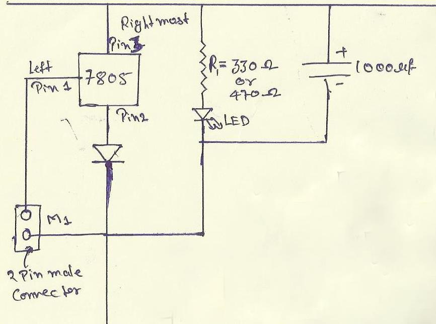
POWER SUPPLY: Before making any circuit we need to design its power supply it consist of many part like step down, ac-dc conversion, voltage stabilizing etc but we will giving the power to our board from an 12-volt adapter so our power supply consist of a voltage regulator,capacitor,diode, led and connector. 
    Power Supply
    Voltage regulator

    • 7805:-It is the voltage regulator ic as pin diagram is shown.
    • diode IN4007 and the silver line part is its negative.
    • resistor R1=330ohm or we can also use 470ohm because it is use with the led.
    • A 2 pin male connector is required for giving the power to the circuit the +ve will connect with 1 pin of 7805.
    • A 1000uf capacitor is also use with power supply to reducing the ripple or maintaining the continuity.
    • Led:-the cutted portion of the led is negative.
hyper terminal window
COMPUTER: Here the computer is use to send the command to the microcontroller via serial communication for this purpose we use the usb2serial cable to connect the computer to my circuit. Because in present their is no serial port into the computer's. Now for connecting my computer to the   serial port we use an application named HYPER TERMINAL so tht we can send the data and also see what exactly we are sending to the microcontroller and we can also see what the microcontroller do after getting the signal from computer. 
By this hyperterminal we send the ASCII codes and by those command's we easily make the decision those decision will be further use.

DB9 CONNECTOR: DB9 connector is use to connect the computer with your  programmer board it uses the RS232 cable to connect the DB9 port has 9 pins each pin has its own function but we will use only pin no 2 , 3 and  5.
  • pin no 2 is known as recieved data bit when controller transmit the data bit then computer recive from this pin. This is connected to the 14th pin of max232.
  • pin no 3 is named as transmit data the data will transmit form the computer with the help of this pin and this is connected 13th pin of max232.
  • pin no 5 we make this pin normally ground.

LEVELSHIFTER: The MAX232 is an Integrated Circuit that convert signal from an RS232 serial port to signal suitable for use in ttl compaitable digital logic circuits.The MAX232 is a dual driver/receiver and typically converts the RX, TX, CTS and RTS signals.For more details of MAX232 you can download the datasheet of it form here. download  
  • here the values of all the capacitors are 0.1 uf.
  • 16 pin is vcc should be maintained at 5volt dc.
  • the 15th pin becomes ground.
  • T1out-pin is use to send the data serially to the computer.
  • R1in-pin is use to recieve the data from the computer serially.
  • T1in-pin is use to tramsmitt the data from microcontroller to MAX232 which is actually going to computer.
  • R1out-pin is use for send the incoming data from MAX232 to microcontroller which is actually come from computer.
  • Download the MAX232 datasheet here.download 
MICROCONTROLLER: The processing is the most important part of the robot. Till now we get the data from the computer now based on that data we have to make some decision so here the role of microcontroller is coming up. We use an 8051 microcontroller for our circuit to give them a decision capability. Our microcontroller is made up by nxp the product name is P89V51RD2
The basic circuit to initialize the microcontroller is shown below. We just need an reset circuit and oscillator to run the program.

8051 micro controller circuit
 we use serial port  as an input port and port 2 as an output port.
so the Data from the computer  will connect pin 11(rx) 12(tx) of the microcontroller and motor should be connect with pin 21,22,23,24. 
For forward the data to the serial port is 'w' or for backward it is 's' then for left its 'a' and for right it is 'd'.
Encoder(HT12E IC):- The HT12E is an 4bit encoder which encode the input data applied on it .The pin description of the HT12E is shown in the figure .
Encoder
  • pin (1 to 8) A0-A7 known as address bits so we do not need to consider them.
  • pin no (9 and 18) are use to bias the IC  as pin-18 as VCC and pin-9 as GND.
  • pin - 17 is connected to the rf transmitter module Din.
  • pin-16 and pin-15 are connected by an Osc resistor known as Roscc(1.1 Mohm)
  • pin-14 is connected to ground to enable the transmitt.
  • pin-13 to pin-10 are known as AD0 to AD3 those having the 4bit data which is required to transmit.
      
RF Transmitter Module(TX):- The transmitter module is working  on the frequency of 433MHz and is easily available in the market at the cost of 250rs .
RF Transmitter module
  • The vcc pin is connected to the +terminal in the circuit.
  • The data pin is connected to the HT12E(pin no-17) that is transmitted or we can say that encoded data.
  • The next pin is shown in figure is GND that is connected to the ground terminal.
  • Now the last pin ANT this is connected to a small wire as an antenna.


Here is the full circuit diagram of this robot transmitter module with each component...
FULL TRANSMITTER CKT
RECEIVER MODULE: Now at the Receiver side firstly we have RF receiver module which get the encoded data on it and convert that data into the voltage signal and that data is then applied to the decoder IC(HT12D) which decoded it into the 4bit data which is further apply on the motor driver IC(L293D) basically a h-bridge to provide the high current to the motor. And finally the motor will operate as the user want who's sitting on the computer.
Now the modules of a Receiver module can be shown in the block diagram:

Receiver Module 
As we can see in above block diagram the Receiver module can further divided into 5 parts:
                                                                                       > Power Supply
                                                                                       > RF Receiver
                                                                                       > Decoder(HT12D)
                                                                                       > Motor driver(L293D)
                                                                                       > Motor's(100 rpm)
POWER SUPPLY: The power supply will be same as discussed above:.

RF RECEIVER MODULE: The RF receiver module will receive the data which is transfered by the Transmitter module. It is also working as similar to the transmitter module-
  • Connect the +vcc pin to the 5volt terminal
  • Connect the ground pin to the ground terminal 
  • The data pin is then connected to the HT12D (pin-14)
  • So that we can get the decoded 4 bit data

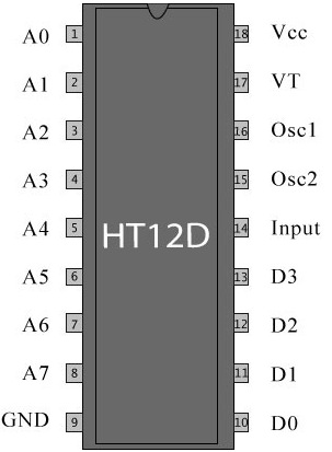
DEECODER(HT12D): In very simple way we can say that an HT12D converts that serial data into parallel which is received by the rf receiver module.The input data is decoded when no error or unmatched codes are found. A valid  transmission in indicated by a high signal at VT pin that is pin no 17.
HT12D
  • pin 18     : It is use to give the +vcc or biasing to the  IC HT12D this pin is connected with the +5 volt
  • Pin 17     : It is the valid transmission pin it will high when the transmission is ok so that we connected this pin to an led for indication.
  • Pin 16-15: we connect these two pin directly by a 51k resistor
  • Pin 14     : This pin is connected with the rf receiver module data pin to receiving the serial data.
  • Pin 10-13: These pins are data pin which is transferred by the Transmitter module for the motor's.

ACTUATOR(L293D): The Actuator's are those devices which actually gives the movement or to do a task like motor's. In the real world their are various types of motor's available which works on different voltages. So we need motor driver for running them through the controller. To get interface between motor and microcontroller . We use L293D motor driver IC in our circuit.
motor driver circuit
As in above circuit 2 pin male
As in above circuit a 2 pin male connector in connected to the pin 8 this will provide the operating voltage for the motor like if we want to run our voltage on 12volt. so we just have to connect a 12volt power source 


Now here is the full receiver circuit after the whole discussion about it small modules....

FULL RECEIVER CKT
now You can make your own computer controlled robot easily.

 C PROGRAM OF COMPUTER CONTROLLED ROBOT:

//Program to interface computer with 8051 microcontroller (8051 architecture)

#include<reg51.h>
unsigned char rcv_data;

void receive()    //Function to recieve data serialy from RS232
{
    while(RI==0);
    rcv_data = SBUF;
    RI=0;
}

void compare()
{
    if(rcv_data=='w')                        // forward
    P2=0x0a;
    else if(rcv_data=='a')                  //      left
    P2=0x08;
    else if(rcv_data=='s')                  //      right
    P2=0x05;
    else if(rcv_data=='d')                  //      backward
    P2=0x02;
    else
    P2=0x00;
}
 

For program of this robot click here 


*************************   VIDEO OF COMPUTER CONTROLLED ROBOT****************


******  IMAGES******


transmitter circuit


Receiver ckt


COMPUTER CONTROLLED ROBOT

Wednesday, 2 May 2012

A Gesture Controlled robot is a kind of robot which can be controlled by  your hand gestures not by old buttons.You just need to wear a small transmitting device in your hand which included an acceleration meter.This will transmit an appropriate command to the robot so that it can do whatever we want. The transmitting device included a comparator IC for analog to digital conversion and an encoder IC(HT12E) which is use to encode the four bit data and then it will transmit by an RF Transmitter module.
At the receiving end an RF Receiver module receive's the encoded data and decode it by an decoder IC(HT12D). This data is then  processed by a microcontroller (P89V51RD2) and finally our motor driver to control the motor's. 
Robot 
Gesture device
As we can see in the images one is robot and the another is to trnsmit the gesture data to robot.
Now its time to break the task in different module's to make the task easy and simple any project become easy  or error free if it is done in different modules. As our project is already devided into two different part transmitter and receiver. We will discuss both of them one by one. Apart from Power Supply as it was discussed in last blog you can see that by just click here

1> Transmitter device or Gesture device: This part contain four module in it--
                                                                                           1- Accelerometer
                                                                                           2- Comparator                                                                                 
                                                                                           3- Encoder(HT12E)
                                                                                           4- RF Transmitter 
      Accelerometer:-  An Accelerometer is a kind of sensor which gives an analog data while moving in X,Y,Z direction or may be X,Y direction only depend's on the type of the sensor.Here is a small image of an Accelerometer shown. We can see in the image that their are some arrow showing if we tilt these sensor's in that direction then the data at that corresponding pin will change in the analog form.
The Accelerometer having 6 pin-
1- VDD- We will give the +5volt to this pin


2- GND- We simply connect this pin to the ground for biasing.
3- X- On this pin we will receive the analog data for x direction movement.
4- Y- On this pin we will receive the analog data for y direction movement.
5- Z-  On this pin we will receive the analog data for z direction movement.
6- ST- this pin is use to set the sensitivity of the accelerometer 1.5g/2g/3g/4g.
     
      Comparator:- For the purpose to change the analog voltage into digital we use comparator which compare that analog voltage to a reference voltage and give a particular high or low voltage.
LM324 IC
The figure shown here is comparator IC. The pin 1,7,8 and 14 are use to give out put to the microcontroller.We should connect a reference voltage to the -ve terminal for high output when input is high(+ve terminal for high output when input is low) from the LM324 IC.
In this circuit we compare the data from x with two terminal one for positive x direction and negative x direction and same for y direction.
HT12E encoder
Encoder(HT12E IC):- The HT12E is an 4bit encoder which encode the input data applied on it .The pin description of the HT12E is shown in the figure .
  • pin (1 to 8) A0-A7 known as address bits so we do not need to consider them.
  • pin no (9 and 18) are use to bias the IC  as pin-18 as VCC and pin-9 as GND.
  • pin - 17 is connected to the rf transmitter module Din.
  • pin-16 and pin-15 are connected by an Osc resistor known as Roscc(1.1 Mohm)
  • pin-14 is connected to ground to enable the transmitt.
  • pin-13 to pin-10 are known as AD0 to AD3 those having the 4bit data which is required to transmit.
      RF Transmitter Module(TX):- The transmitter module is working  on the frequency of 433MHz and is easily available in the market at the cost of 250rs .
  • The vcc pin is connected to the +terminal in the circuit.
  • The data pin is connected to the HT12E(pin no-17) that is transmitted or we can say that encoded data.
  • The next pin is shown in figure is GND that is connected to the ground terminal.
  • Now the last pin ANT this is connected to a small wire as an antenna.
  • CIRCUIT OF GESTURE DEVICE (TRANSMITTING MODULE)
1> Receiver or Robot:  This part contain four module--         
  1. Receiver
  2. Decoder(HT12D)
  3. Process(microcontroller 8051)
  4. Actuator (Motor driver L293D)
  RF Receiver Module(RX):- The RF receiver module will receive the data which is transfered by the gesture device. It is also working as similar to the transmitter module-
  • Connect the +vcc pin to the 5volt terminal
  • Connect the ground pin to the ground terminal 
  • The data pin is then connected to the HT12D (pin-14)
  • So that we can get the decoded 4 bit data
    Decoder (HT12D):- In a very simple way we can say that an HT12D converts that serial data into parallel which is received by the rf receiver module.The input data is decoded when no error or unmatched codes are found. A valid  transmission in indicated by a high signal at VT pin that is pin no 17.
HT12D
  • pin 18     : It is use to give the +vcc or biasing to the  IC HT12D this pin is connected with the +5 volt
  • Pin 17     : It is the valid transmission pin it will high when the transmission is ok so that we connected this pin to an led for indication.
  • Pin 16-15: we connect these two pin directly by a 51k resistor
  • Pin 14     : This pin is connected with the rf receiver module data pin to receiving the serial data.
  • Pin 10-13: These pins are data pin which is transferred by the gesture module
Process (Microcontroller P89V51RD2): The processing is the most important part of the robot. Till now we get the data from the decoder now based on that data we have to make some decision so here the role of microcontroller is coming up. We use an 8051 microcontroller for our circuit to give them a decision capability. Our microcontroller is made up by nxp the product name is P89V51RD2
The basic circuit to initialize the microcontroller is shown below. We just need an reset circuit and oscillator to run the program.
8051 micro controller circuit
 we use the port 1 as an input port and port 2 as an output port.
so the Data from the decoder  will connect with pin 1,2,3,4 and motor should be connect with pin 21,22,23,24. 
For forward the data to the Port2 is 0a or for backward it is 05 then for lest its 02 and for right it is 08.

ACTUATOR'S(L293D): The Actuator's are those devices which actually gives the movement or to do a task like motor's. In the real world their are various types of motor's available which works on different voltages. So we need motor driver for running them through the controller. To get interface between motor and microcontroller . We use L293D motor driver IC in our circuit.
motor driver circuit
As in above circuit 2 pin male 
As in above circuit a 2 pin male connector in connected to the pin 8 this will provide the operating voltage for the motor like if we want to run our voltage on 12volt. so we just have to connect a 12volt power source 
Now here is the full circuit diagram of the robot (receiver module)

RECEIVER MODULE


ACTUAL CIRCUIT OF RECEIVING  MODULE
PROGRAM: Now here is the program of the Gesture Controlled robot. The program is in Embedded-C. The microcontroller we used is 8051.

/**********************************************************************************
    Gesture Controlled robot C program using 8051 microcontroller

***********************************************************************************
INPUT DATA to PORT 1 LM324     OUTPUT DATA to PORT 2 for L293D

MSB  LSB              MSB    LSB
1111  0001(0xf1)          0000   1010(0x0a)    forward
1111  0010(0xf2)          0000    0010(0x02)    right
1111  0100(0xf4)          0000    1000(0x08)    left
1111  1000(0xf8)          0000   0101(0x05)    backward

**********************************************************************************/
#include<reg51.h>        //INCLUDE reg51.h for 8951   

void main()
{
    P1=0xff;    // set port as input port
    P2=0x00;    // set port as output port
  
    while(1)    // infinite loop
    {
    if(P1==0xf1)
    {
        P2=0x0a;
    }
    else if(P1==0xf2)
    {
        P2=0x02;
    }   
    else if(P1==0xf4)
    {
        P2=0x08;
    }   
    else if(P1==0xf8)
    {
        P2=0x05;
    }
    else
    {
        P2=0x00;
    }
   }


Here is the video presentation of the gesture robot....


Here are some more pics of the robot . Leta take a look.


***************************** thanx and best of luck*****************************

GESTURE CONTROLLED ROBOT(Accelerometer based)

 
2embeddedrobotics © 2015 - Designed by Templateism.com