Friday 1 May 2015

Low Power devices in small packages is the need of present and future electronic devices. Electronics Industry is making devices which can be planted in human bodies. CMOS Technology won‟t be able to deliver such devices because it shows short channel effects in Nano scale. So, to overcome the problems of CMOS technology we use CNTs (Carbon Nano Tubes). In electronic devices, power is consumed by various elements like flip-flop, latches, clock sources. So in order to reduce power of a system we used to reduce power consumed by flip-flops.
In this paper we design an existing flip-flop “Low power clocked pass transistor flip-flop (LCPTFF)” on CNTFET using Stanford CNTFET model for reference. We propose a design of CNTFET based Forced Stack Low Power Clocked Pass Transistor Flip-Flop (CN-FS-LCPTFF) and observe 12% to 25% power reduction in various conditions like temperature change, CNTFET diameter change, and different voltage supply.


Vikas Sharma, Umesh Dutta, “Designing of Low Power CNTFET Based D Flip-Flop Using Forced Stack Technique”Vol. 5 – Issue 4 (April – 2015), International Journal of Engineering Research and Applications (IJERA) , ISSN: 2248-9622 , www.ijera.com

Designing of Low Power CNTFET Based D Flip-Flop using Forced Stack Technique

Digital designs in this era require small size and low power components. Scaling of CMOS technology results into various short and narrow geometry effects. One of those effects is subthreshold current (leakage current) which results into unnecessary power dissipation. CNTFET (Carbon Nanotube FET) is a novel approach to solve the problem of scaling. Leakage current power dissipation is reduced by sleep transistor configuration. Flip Flops are an essential part of digital designs. Reduction of power consumption in a Flip Flop is highly desirable. This paper is intended to accomplish a systematic analysis of low power consumption positive edge triggered D Flip Flop made using CNTFETs and in sleep transistor configuration. The proposed circuit has less power dissipation and can be used efficiently with low power circuitry. This proposed work is then compared with the performance analysis of conventional Complementary Metal Oxide Semiconductor and Carbon Nanotube FET circuit designs. The overall simulation and computation is performed using HSPICE.


Avichal Sahai, Vikas Sharma,”Design of Low Power CNTFET Based D Flip Flop using Sleep Transistor Technique”, volume -4 ,issue 4, IJERT.

Designing of Low Power CNTFET based D Flip-Flop using Sleep Transistor Technique

Sunday 1 March 2015

INTEL EDISON
Edison is a SD Card sized computing module made by Intel® with the vision of making wearable devices more powerful and small enough. Edison is more powerful then it look in size its come with  32-bit Intel® Atom™ Processor clocked at 500MHz, 1GB RAM, 4 GB eMMC FLASH Memory, WiFi, Bluetooth, UARTS, I2C, SPI, 40 GPIO.
Intel Edison support Linux OS based on yocto and we can program the edison board on c,c++, nodejs, Python ,Arduino,etc.

INTERFACING WITH EDISON
Edison is very small in size because it is developed to use in wearable devices so a very tiny connector(hirose connector) is used which is the hard part of edison for us to interface with different modules. So while buying the edison also buy the breakout board for it. I buy the Edison with an Arduino break out board.

This Arduino expansion board is verygood to start working with Edison.

SETUP HARDWARE


For powering the edison externel adaptor is a good option because power from USB sometime not sufficient.


DOWNLOAD


After downloading all the four file above please Install them.

TALKING WITH EDISON BOARD

After installation open the device manager  and you can see the USB serial port note down the number of your serial port.


 Now Open the putty terminal emulator
And go to category on the left side on the bottom chose Serial and at the top right of the Putty Configuration dialog box, specify the following: which shown in figure

a. For Connection type, select the Serial radio button.
b. In the Serial Line field, type the COM # (e.g. COM7) of your board.
c. In the Speed field, type 115200.
d. From the side menu, expand the Connection options and select Serial. Specify the following settings:
e. In the Serial line to connect to field, type the COM # (e.g. COM7) of your board.
f. In the Speed (baud) field, type 115200.
g. In the Data bits field, type 8.
h. In the Stop bits field, type 1.
i. From the Parity drop-down list, select None.
j. From the Flow control drop-down list, select XON/XOFF.


Now goto the Session on the left hand side . Type a name for the configuration in the Saved Sessions field, chose the comport and speed of 115200 and serial and click on SAVE.
as in figure.


Now Click Open to connect with Edison when you see black screen please enter two times
Now login screen will displayed
type root  and press Enter

If asking for password then press enter again  you will be seen the promt as in the below figure.

Now you finally Login with linux Youcto in Intel Edison here you can create c program and run it using GCC compiler and also nodejs. and many more platform.Use VI Edistor of linux to create files.


Getting Started with INTEL EDISON

Tuesday 7 October 2014

In this Artical we will see how to establish communication between computer/mobile to Arduino in a LAN or Wireless Network. We are interfacing the ENC28J60 Ethernet controller to Arduino so that our Arduino will be the one of member of that network. Once it will done the arduino can control things in that network or the arduino can be controlled by the other devices of that network it might be computer or mobile. Interfacing Arduino with the ENC28J60 will further gives us the freedom of using the internet on Arduino but before that we need to learn how to do all that networking stuff in a locan network.

Soon I will post about how to control the things in local network, how to send data on a local network, and how to interfaced with Android devices or how to make IOT Devices. IOT Devices are quite famous.
 

A simple block diagram of the data flow  is in the image below.


Ethernet Module( ENC28J60):  Microchip's ENC28J60 is a 28-pin,  Ethernet Controller with on board MAC & PHY, 8 Kbytes of Buffer RAM and an SPI serial interface. With a small foot print package size the ENC28J60 minimizes complexity, board space and cost. It used in so many application like Industrial Automation, Building Automation, Home Control, Security and Instrumentation, IOT Devices.
You can build Your own circuit but I use the Module to save my time.


VIRTUAL SIMULATION: I first simulate my design on the Proteus ISIS to make sure I am working in right direction and also to save my time. In ISIS their is already a component named "ENC28J60 ethernet controller" so I picked it from the library. Now I picked up the Arduino and connect it with the ethernet controller.


if the link dont work please comment

* Connections:   
  
Now make these connection in the ISIS design tool.


SOFTWARE: Now we all done with the Virtual Hardware Design lets make the software. All you need is the Ethercard Library for this example. Download it from here EtherCard. Click here
  • Extract the ZIP file , copy and paste the folder in your Arduino1.xx/library/  
  • once you place the folder in your arduino library folder restart your Arduino IDE
  • Now  go to ethercard > Examples > backsoon
 
 Compile the code  : if facing any problem then go to :  How To Simulate Arduino in ISIS

Make some changes in the program as given below
changes are in Red colour
Arduino code
/*#############################################################################
###############################################################################*/

// Present a "Will be back soon web page", as stand-in webserver.
// 2011-01-30 <jc@wippler.nl> http://opensource.org/licenses/mit-license.php

#include <EtherCard.h>

#define STATIC 0  // set to 1 to disable DHCP (adjust myip/gwip values below)

#if STATIC
// ethernet interface ip address
static byte myip[] = { 192,168,1,200 };
// gateway ip address
static byte gwip[] = { 192,168,1,1 };
#endif

// ethernet mac address - must be unique on your network
static byte mymac[] = { 0x74,0x69,0x69,0x2D,0x30,0x31 };

byte Ethernet::buffer[500]; // tcp/ip send and receive buffer

// char page[] is the HTML page you are uploading ..
char page[] PROGMEM =
"HTTP/1.0 503 My Seriavice \r\n"
"Content-Type: text/html\r\n"
"Retry-After: 600\r\n"
"\r\n"
"<html>"
  "<head><title>"
    "2embeddedrobotics "
  "</title></head>"
  "<body>"
    "<h3>Welcome to 2embeddedrobotics</h3>"
    "<p><em>"
      "The World of IOT Devices .<br />"
      "yipeee   Congrats...."
    "</em></p>"

   "</body>"
"</html>"
;

void setup(){
  Serial.begin(9600);
  Serial.println("\n[backSoon]");
 
  if (ether.begin(sizeof Ethernet::buffer, mymac) == 0)
    Serial.println( "Failed to access Ethernet controller");
#if STATIC
  ether.staticSetup(myip, gwip);
#else
  if (!ether.dhcpSetup())
    Serial.println("DHCP failed");
#endif

  ether.printIp("IP:  ", ether.myip);
  ether.printIp("GW:  ", ether.gwip); 
  ether.printIp("DNS: ", ether.dnsip); 
}

void loop(){
  // wait for an incoming TCP packet, but ignore its contents
  if (ether.packetLoop(ether.packetReceive())) {
    memcpy_P(ether.tcpOffset(), page, sizeof page);
    ether.httpServerReply(sizeof page - 1);
  }
}
/*##############################################################################
###############################################################################*/

now compile the code with prefrence compile. in file option.. so that you will get the .HEX file for ISIS.


Now you have done every thing . Hit the Play Button and it will give you the assigned IP address in serial monitor now write it down on a paper.

 
open the web browser and write the IP address of your arduino in the browser.
 

 Now you can watch this page on any device connected to that network  As I show.

HARDWARE: We already did everything in virtual now we just need to connet each component as per the connection given in starting.
Now upload the program to your Arduino and turn on its Serial monitor so that u can get Your 
"IP in Serial Monitor" and just open browser and put your IP and check the webpage.


Now you have done then note your IP from the serial monitor and Enjoy..
Wish you a very good Luck.


Ethernet(ENC28J60) Interfaced Arduino

Saturday 4 October 2014

Carbon Nanotube Field Effect Transistor(CNTFET) is an promising alternative of an conventional CMOS technology in future. improvement in integration densities in past few years is remarkable but aggressive scaling of these MOS devices reaching to its limit. so the CNT replaces the isilicon so the CNTFET replaces the MOSFETs. 

Stanford university made an CNTFET model which we are using here. The codes are same as for MOSFET but the parameters need to be change like here Dcnt (diameter) of the CNT plays a role like L in the MOSFET.

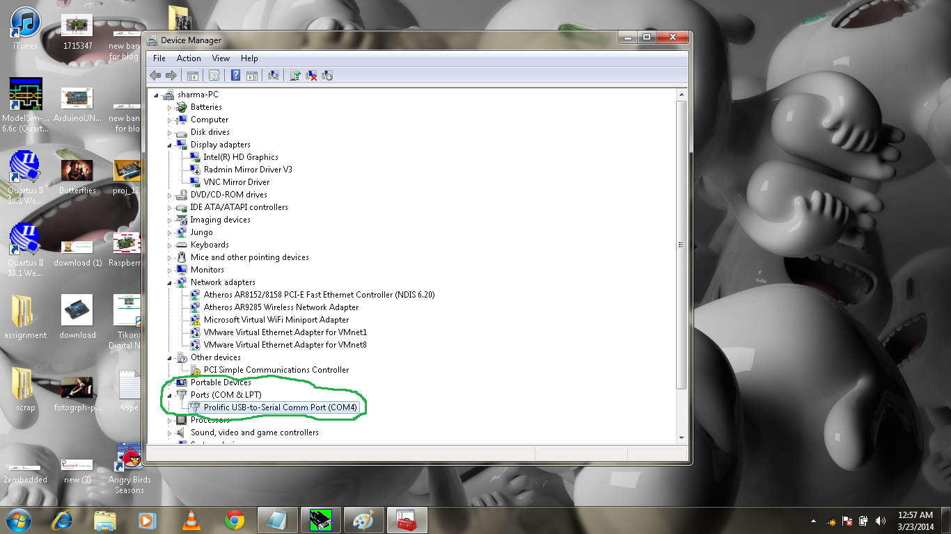
SETUP: First we need to setup the the tools for CNTFET.
  • Install the HSPICE in your system 
  • download the library of CNTFET from standford university website. or CLICK HERE
  • make a directory with the name of project and paste all the file in the project from the package you downloaded from stanford university
WRITE THE CODE: Now write the code for the circuit in my case i am writing a code for an inverter.

***************************************************
***************************************************
*For optimal accuracy, convergence, and runtime
***************************************************
.options POST
.options AUTOSTOP
.options INGOLD=2     DCON=1
.options GSHUNT=1e-12 RMIN=1e-15
.options ABSTOL=1e-5  ABSVDC=1e-4
.options RELTOL=1e-2  RELVDC=1e-2
.options NUMDGT=4     PIVOT=13

.param   TEMP=27
***************************************************


***************************************************
*Include relevant model files
***************************************************
.lib 'CNFET.lib' CNFET
***************************************************
*Some CNFET parameters:


.param Ccsd=0      CoupleRatio=0
.param m_cnt=1     Efo=0.6    
.param Wg=0        Cb=40e-12
.param Lg=32e-9    Lgef=100e-9
.param Vfn=0       Vfp=0
.param m=19        n=0       
.param Hox=4e-9    Kox=16

***********************************************************************
* Define power supply
***********************************************************************


*Vdd     1     0     0.9


***********************************************************************
* Main Circuits
***********************************************************************
* nFET

X2 Out N_1 Gnd Gnd NCNFET Lch=Lg  Lgeff='Lgef' Lss=32e-9  Ldd=32e-9 
+ Kgate='Kox' Tox='Hox' Csub='Cb' Vfbn='Vfn' Dout=1  Sout=0  Pitch=20e-9  n1=m  n2=n  tubes=3

* pFET

X1 Out N_1 Vdd Vdd PCNFET Lch=Lg  Lgeff='Lgef' Lss=32e-9  Ldd=32e-9 
+ Kgate='Kox' Tox='Hox' Csub='Cb' Vfbp='Vfp' Dout=1  Sout=0  Pitch=20e-9  n1=m  n2=n  tubes=3

VVoltageSource_1 Vdd Gnd  DC 0.9
VVoltageSource_2 N_1 Gnd  PULSE(0 0.9 0n 5n 5n 50n 100n)

***********************************************************************

.tran 1n 500n

.MEASURE avg_pow AVG power FROM=1n TO=500n

.MEASURE TRAN t1 TRIG V(N_1) VAL = 0.45 TD = 0n RISE = 1
+ TARG V(Out) VAL = 0.45 FALL = 1

.MEASURE TRAN t2 TRIG V(N_1) VAL = 0.45 TD = 0n FALL = 1
+ TARG V(Out) VAL = 0.45 RISE = 1


.MEASURE TRAN tp PARAM='(t1+t2)/2.0'


.OPTION PROBE POST MEASOUT
.end
***********************************************************************
***********************************************************************
Now after writing the code save it with the extension "your_file_name.sp".


HSPICE : Now lets start to simulate your design with HSPICE.

1) Open the HSPICEpui


2) Click the OPEN Button to open the design file or the code file you wrote. Browse your design file in the design section and left rest of the thing.


3) Now click the Simulate button .

4) Now open the 'Avanwaves' to view your pulses or the output.


5) Now click the operating points you want to view like in my case i double click on vin and vout.
and  see the wave form.

6) Now click on the Editll to view your result like Power , Propagation Delay , Hold Time etc.


As you can read that the average power(avg_power) is .17 microwatt and propagation delay(tp) is about .18 ps.

*********************************************************
                                           Clean India
*********************************************************
Please share and comment if you see this tutorial informative
*********************************************************

CNTFET Inverter "Design & Simulation using HSPICE"

Monday 24 March 2014

Proteus (ISIS Design) tool is very popular platform for simulating an electronic design before making its real hardware but its hard to get every components and its functionality in proteus. So we  interface hardware components  with proteus design like RFID Module, GSM Module, Bluetooth Module, Finger Print Module etc. via virtual serial port emulation( VSPE) software.


Virtual Serial Port Emulation (VSPE): VSPE is use to help developers to create applications that use serial ports. It is able to create various virtual devices to  transmit/receive data. One Serial port can be opened into many different applications and use their different functionality. With VSPE you are able to share physical serial port data for several applications, create virtual serial port device  pairs and so on.

DOWNLOAD VSPE : Click Here

Configuring VSPE: Step by Step process to configure the VSPE shown below.

1) Open the VSPE from my program or by desktop icon.


2) Now go to the Device>Create after clicking the Create below window open.


3)  Now specify device type and select splitter and click on Next button


4) Now Plug the USB2Serial into the USB Port and open the Device Manager and check for the Port number (ex: COM4).


5) Now check the VSPE window back and specify device characteristics. Now their are two blocks 
  • Virtual Serial Port > specify the number you want to give the virtual port you want to make (ex com1)
  • Data Source Serial Port > In this field put your COM Port number which you get into the last step. COM4.

6) Now left Click on Settings.. and select 9600 in speed field.where 9600 is the baud rate of communication. Now left Click on Finish button.


7) After Clicking  on Finish button the virtual device will initialized.


The Virtual Device finally Configured now we Need to configure the proteus (ISIS Design).

COMPIM: The COMPIM model is a Physical Interface Model of a serial port. Incoming serial data is buffered and presented to the circuit as a digital signal, whilst serial digital data generated by a CPU or  UART model appears at the PC's physical COM port. The COMPIM model also provides for baud rate translation, and for optional hardware or software handshaking on both the physical and virtual sides of the device.

1) Add the COMPIM in ISIS from its component mode.


2) Now Add the Virtual Terminal from the Virtual instrument mode.
   connect the RXD and TXD of virtual terminal to RXD/TXD to COMPIM.


3)  Now right click on COMPIM and select the Edit Properties.


4) Change the Baud rate of physical port and virtual port to 9600 as shown in the fig below.


Do the same step for virtual terminal.


5) now press the Play button as in the fig below


6)  Now punch the card and see the data at virtual terminal in the fig below  as i mentioned already that i used the RFID Module for this tutorial as an example.


I hope the above post would help you. I really welcome your suggestions and queries.
****************
THANK YOU
****************


Serial Devices Interfacing to Proteus Using VSPE

 
2embeddedrobotics © 2015 - Designed by Templateism.com