
MS PowerPoint is very important part of our professional and student life .we face several problems while giving the presentation or seminar on some topic like we need an operator to operate the slides and sometimes this will create problems if speaker and operator are not well prepared. To overcome this problem we made the gesture device which can be connected to the computer and operated by the speaker gesture.
The device basically have two part gesture transmitter and computer receiver.

In this device we first recognize the direction of right hand movement by placing ir sensor on left hand. Then the data is transmitted by the transmitter and the receiver receive the data and give to the computer and one application in the computer control the ppt. You can download that application here.DOWNLOAD APPLICATION.
HERE IS THE DEMO VIDEO OF THE APPLICATION...
GESTURE TRANSMITTER MODULE: The gesture transmitter Module consist of four different part.
1. IR Sensor Pair
2. LM324 OP-Amp IC.
3. HT12E Encoder IC.
4. RF Transmitter Module
 |
| IR sensor principle |
As given in block diagram of Gesture transmitter module the IR sensor pair give the data to LM324 which compare the voltage of the IR pair output to the reference voltage and make it to digital. This digital data is further going into the HT12E encoded and transmitted by the Rf transmitter module.
 |
| IR circuit |
 |
| comparator |
From the IR sensor we get the analog data so we have to change that in the digital format like when an object seen than it should return 0v or 4v or in other word's we can say that in high or low voltages because we kno that in digital high voltage = 1 and low voltage= 0.
 |
| comparator data |
For the purpose to change the analog voltage into digital we use comparator which compare the analog voltage to a reference voltage and give a high or low voltage a desired for controller.
 |
| lm324 comparator ic |
The figure shown here is a comparator IC the pin 1,7,8 and 14 are use to give out put to the micro controller. we should connect a reference voltage to the -ve terminal of this IC lm324 and the out put of the IR sensor to its +ve terminal's.
The circuit show below is for your sensor module this is nothing just the summer of what we discuss in sensor subtopic.
ENCODER(HT12E IC): The HT12E is an 4bit encoder which encode the input data applied on it .The pin description of the HT12E is shown in the figure .

As shown in the block diagram RF receiver module get the transmitted signal sended by transmitter and then HT12D decodes that data in four bit digit and given to the ARDUINO board for making an decesion and send to computer via serially. One application is running in the computer which understand the signal sended by Arduino and control the PPT slides while presenting
Hardware Part: - 1.) Computer
2.) ARDUINO BOARD
3.) HT12D decoder IC
4.) RF Receiver module
1.) RF Receiver Module : The RF receiver module will receive the data which is transfered by the Transmitter module. It is also working as similar to the transmitter module-
 3.)ARDUINO Board : Arduino is an open-source platform based on avr (atmega series). It’s a combination of easy to use software and hardware environment for electronics student, developer, hobbyists to create interactive devices and environments.

Software Section:
For downloading the PC application to connect your hardware to PC please CLICK HERE
*******************************************************************************
 |
| IR sensor with comparator circuit |
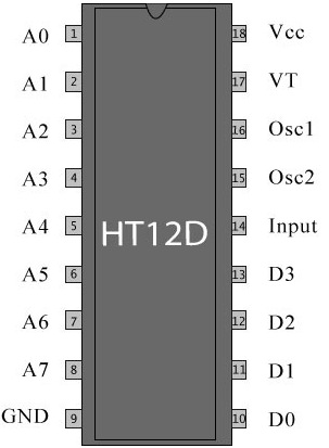 |
| HT12D |
- pin (1 to 8) A0-A7 known as address bits so we do not need to consider them.
- pin no (9 and 18) are use to bias the IC as pin-18 as VCC and pin-9 as GND.
- pin - 17 is connected to the rf transmitter module Din.
- pin-16 and pin-15 are connected by an Osc resistor known as Roscc(1.1 Mohm)
- pin-14 is connected to ground to enable the transmitt.
- pin-13 to pin-10 are known as AD0 to AD3 those having the 4bit data which is required to transmit.
RF TRANSMITTER MODULE(TX): .The transmitter module is working on the frequency of 433MHz and is easily available in the market at the cost of 250rs .
 |
| RF Transmitter module |
- The vcc pin is connected to the +terminal in the circuit.
- The data pin is connected to the HT12E(pin no-17) that is transmitted or we can say that encoded data.
- The next pin is shown in figure is GND that is connected to the ground terminal.
- Now the last pin ANT this is connected to a small wire as an antenna.
Final circuit setup

COMPUTER RECEIVER MODULE: The Computer Receiver module consist different parts.
 |
| receier module |
Hardware Part: - 1.) Computer
2.) ARDUINO BOARD
3.) HT12D decoder IC
4.) RF Receiver module
1.) RF Receiver Module : The RF receiver module will receive the data which is transfered by the Transmitter module. It is also working as similar to the transmitter module-
- Connect the +vcc pin to the 5volt terminal
- Connect the ground pin to the ground terminal
- The data pin is then connected to the HT12D (pin-14)
- So that we can get the decoded 4 bit data

2.)Encoder(HT12E IC):- It decodes the data is received by the RF receiver module.The input data is decoded when no error or unmatched codes are found. A valid transmission in indicated by a high signal at VT pin that is pin no 17.
|
| HT12D |
- pin 18 : It is use to give the +vcc or biasing to the IC HT12D this pin is connected with the +5 volt
- Pin 17 : It is the valid transmission pin it will high when the transmission is ok so that we connected this pin to an led for indication.
- Pin 16-15: we connect these two pin directly by a 51k resistor
- Pin 14 : This pin is connected with the rf receiver module data pin to receiving the serial data.
- Pin 10-13: These pins are data pin which is transferred by the Transmitter module.
3.)ARDUINO Board : Arduino is an open-source platform based on avr (atmega series). It’s a combination of easy to use software and hardware environment for electronics student, developer, hobbyists to create interactive devices and environments.
Arduino can be easily interfaced with sensors, controlling led’s , motor driving, relays. The on board microcontroller is programmed with help of arduino programming language, and arduino development environment.
4.)Computer : Finally the Computer get the data from the Arduino board and act according to the program one appliationis also need to connect the port to ppt.
Here is the full setup of receiver module.

*******************************************************************************
ARDUINO PROGRAM written in arduino ide.
*******************************************************************************
int left_sense=9; // left sensor pin
int right_sense=8; // right sensor pin
void setup()
{
Serial.begin(9600);
pinMode(left_sense,INPUT);
pinMode(right_sense,INPUT);
}
void loop()
{
while(1)
{
int left_data = digitalRead(left_sense); //reading left sensor data
int right_data = digitalRead(right_sense); //reading right sensor data
while(left_data == 1) //hand on left sensor
{
left_data = digitalRead(left_sense);
right_data = digitalRead(right_sense);
if(right_data == 1) // passng through right sensor
{
Serial.println("D");
while(right_data == 1) // wait to over the swipe
{
right_data=digitalRead(right_sense);
}
}
}
while(right_data == 1)
{
left_data = digitalRead(left_sense);
right_data = digitalRead(right_sense);
if(left_data == 1)
{
Serial.println("B");
while(left_data == 1)
{
left_data = digitalRead(left_sensor);
}
}
}
}
}
*******************************************************************************
*******************************************************************************
PC AAPLICATION TO CONTROL PPT.For downloading the PC application to connect your hardware to PC please CLICK HERE
*******************************************************************************

sir program m error hai
ReplyDeleteaap prgram correction kigiye.....
thanx friend i did the correction ..
Deletevideo is not playing.............
ReplyDeleteya actually i removed it ...i will uploading in few days...
Deletesir video pllzzzzzzzzzzzzzzzz
ReplyDeleteVikas I have got signals till receiver, but still the arduino is not doing its work with signals? But the software in VB is working, I have also tried by giving pull up resistors, but still not happening, can you suggest anything to me? Moreover the sixth line in arduino program Serial.right_dataegin(9600); has some error!!!!
ReplyDeleteUploading a video will be of great help.
ReplyDeletewhere is the video
ReplyDeletesir the program consists of error
ReplyDeleteat serial.right_dataegin(9600)
Where we keep ir sensor . To our hand or in transmitter circuit
ReplyDeleteWhere we keep ir sensor . To our hand or in transmitter circuit
ReplyDeleteThis comment has been removed by the author.
ReplyDeleteWhere we keep ir sensors. To our hand or in transmitter circuit
ReplyDeletemyTectra Placement Portal is a Web based portal brings Potentials Employers and myTectra Candidates on a common platform for placement assistance
ReplyDelete