
All the student's may not properly works on microcontroller because shortage of programmer kit(burner kit) whatever the problem they have ,so now you can make your own programmer kit for 8051 microcontroller and can make more practical application and learn more efficiently in this field.For making the programmer kit we make the circuit step by step.
FOR P89V51RD2 microcontroller
FOR P89V51RD2 microcontroller
 |
| Power Supply |
- Power supply
- DB9 connector
- Line driver circuit
- 8051
- final circuit of Programmer kit
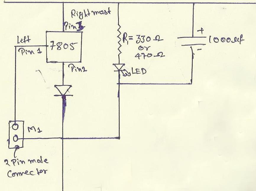
1. POWER SUPPLY: Before making any circuit we need to design its power supply it consist of many part like step down, ac-dc conversion, voltage stabilizing etc but we will giving the power to our board from an 12-volt adapter so our power supply consist of a voltage regulator,capacitor,diode, led and connector.
- 7805:-It is the voltage regulator ic as pin diagram is shown.
- diode IN4007 and the silver line part is its negative.
- resistor R1=330ohm or we can also use 470ohm because it is use with the led.
- A 2 pin male connector is required for giving the power to the circuit the +ve will connect with 1 pin of 7805.
- A 1000uf capacitor is also use with power supply to reducing the ripple or maintaining the continuity.
- Led:-the cutted portion of the led is negative.
 |
7805 voltage regulator
|
2. DB9 CONNECTOR: DB9 connector is use to connect the computer with your programmer board it uses the RS232 cable to connect the DB9 port has 9 pins each pin has its own function but we will use only pin no 2 , 3 and 5.

- pin no 2 is known as recieved data bit when controller transmit the data bit then computer recive from this pin. This is connected to the 14th pin of max232.
- pin no 3 is named as transmit data the data will transmit form the computer with the help of this pin and this is connected 13th pin of max232.
- pin no 5 we make this pin normally ground.
3. LINE DRIVER CIRCUIT: The MAX232 is an Integrated Circuit that convert signal from an RS232 serial port to signal suitable for use in ttl compaitable digital logic circuits.The MAX232 is a dual driver/receiver and typically converts the RX, TX, CTS and RTS signals.For more details of MAX232 you can download the datasheet of it form here. download

- here the values of all the capacitors are 0.1 uf.
- 16 pin is vcc should be maintained at 5volt dc.
- the 15th pin becomes ground.
- T1out-pin is use to send the data serially to the computer.
- R1in-pin is use to recieve the data from the computer serially.
- T1in-pin is use to tramsmitt the data from microcontroller to MAX232 which is actually going to computer.
- R1out-pin is use for send the incoming data from MAX232 to microcontroller which is actually come from computer.
- Download the MAX232 datasheet here.download
 |
| 8051 microcontroller |
As we can see in the fig next that the 8051 microcontroller has 40 pin it has 32 pin I/O lines or we can 32 input and output lines .It consist of four 8bit port's thats why we call it 8bit microcontroller. For our circuit we only need 8 pins these are as follow.
- We need a 40 pin IC base
- RST this is the pin no 9 called as reset pin this pin reset the program counter 0f 8051 microcontroller and it is active high.
- XTAL1 and XTAL2 are for providing the oscillations to the controller.
- 10 and 11th pin are use for serial communication.
- 40th and 31st is to provide vcc basically set at 5volt.
- 20th pin is become ground.
 |
| reset circuit |
 |
| XTAL connection to8051 |


good work buddy
ReplyDeleteITS WILLL B REALLY HELPFUL.......... THANKS A LOT.....
ReplyDeletemast hai sir
ReplyDeleteupgrade it more n more
This is really useful for a beginner like me.
ReplyDeleteHave a question
How do we write into the micro controller from PC;
what software are we using?
C or Kiel?
you can use the flash magic moftware to dump the program into microcontroller and that will be coming in my next post very soon....
ReplyDeleteand for writing a progam just use the keil software and its tutorial is shown in my blogs...
ReplyDeleteplz share the link for magic flash software
ReplyDeletecan we use flash magic to program at89c51?
ReplyDeleteno we can not...
Deletecan at89c51 be programmed by this programmer..if yes then which software should we use????
ReplyDeletei used 10micro f capacitor instead of 0.1uf
ReplyDeletewill it work??????????
can we use this burner for at89c51 microconroller....please replay me.........
ReplyDeletecan we burn any 8051 family ic using this kit?
ReplyDeleteHi, Can i program into AT89C2051 controller
ReplyDeleteCan we program IC P89V51RD2 using this programmer circuit,by loading the hex file in P89V51RD2 using Flash magic.Can we use this board for other 8051 families?Should i use keil software.From where can i download keiluvison4 IDE Full version.Can u tell me the link to download the keiluvision4?
ReplyDeleteNice. I wil try building my own and program it.
ReplyDeleteWe used to program using readymade kit in collage.
I was going to purchase for my own also but now I will not.
It would be great if u provide a PCB layout.
Thank you for this article
is this ckt work without programming?
ReplyDeleteif we are using 8051 IC then there is also need of program?
sir can u plz explain me about this.....
my mail ID is
yasink56@gmail.com
can i program AT89s51 . if yes which software i use
ReplyDeleteis the pin 9 of 8051 connected to 10uF capacitor or between 330ohm and switch or both
ReplyDeletein my laptop there is no db9 port so what can I do?
ReplyDeleteCan any tell me what is parallel with C5 capacitor in Final Circuit
ReplyDeleteThanks for the valuable tips you give on this blog.
ReplyDeleteCall girls London