Friday, 1 November 2013

Led Dot Matrix Display are very famous for Displaying  Messages  in Metro and Buses everywhere and making of these boards are quite interesting. In this tutorial we will make some character frames and running them into a continuous loop then it will look like a dancing man as shown in the images.


*Note we are assuming that you already installed the Keil Uvision and ISIS(proteus) Software in your computer system.

LED MATRIX DISPLAY : In the Dot Matrix LED Display their are multiple leds connected in the row and column fashion just like its name 'matrix'. Assuming 8X8 matrix then the anodes of 8 LEDs are common and named as rowX :  X(1 to 8). Similarly the cathodes of 8 LEDs are common and named as colY Y(1 to 8) as shown in the image below.


Lets turn on a LED shown in the below figure point by a blue circle. 
The led pointed in a blue circle have  cathode  connected with col4 and anode is connected to row3 so if I connect these to pin with microcontroller. We have to set or high the row3 and clear or low the col4.


DISPLAY A CHARACTER: Now assume we want to make this character on the display as shown in  the figure below.
we will first set the row and send the corresponding data to its column so we need to run a loop for sending data to 8 row one by one and send the corresponding 8 bit data to its column for each row. So in real the LEDs are blinking but the blinking is too fast or  we realize that its still an image.

if Row are connected to the port 2 of 8051
if Col are connected to the  port 3 of 8051 

now for turning on 4,5 number LED in row1
we will write      
 /////////////////
P2 = 0b0000 0001;  ///     for selecting first row
P3 = 0b1110 0111;  ///     for turning on the leds in that row


By using the same method we create an table for whole image in the above figure.


CIRCUIT: 


IMAGES: 


DANCING CHARACTER ON DOT MATRIX DISPLAY

Sunday, 6 October 2013

Twitter is very famous website for short messaging. So many people tweeting and exchanging their idea's on twitter. So i made an small application for tweeting my current CPU temperature.


I am using the wheezy-raspbian OS in my raspberry pi and using the python language to write the code for tweeting the CPU temp.It is a very simple DIY project we just need to install Twython on the raspberry pi and small code for interfacing with twitter.


We also need to setup an twitter application to get an API so that we can talk to twitter server and make our application ready to talk with my status.
The raspbian is basically a LINUX based operating system. Most of the linux stuff worked on it.
Now some assumption 
  • You are  having a raspbian installed on your SD card.(CLICK HERE IF NOT)
  • You are connected with internet

Update the OS
Leave this step if you already updated with your OS.
**NOTE: sudo is used for root permession if You already login with root then there is no need of sudo
Type these commands in your terminal

sudo apt-get update

sudo apt-get upgrade

Update or Install the python dependencies or twython
These three commands below install the pip and twython in your raspbian.

sudo apt-get install python-setuptools

sudo easy_install pip

sudo pip install twython

Now register your Twitter App
For using the Twitter API to communicate our raspberry pi we need to register a new Twitter App on its site. CLICK HERE
After hitting the Click Here button you will be redirected to the developer zone of twitter.com 

LOGIN with your twitter account in that website


Now click on the My Application


Now click on the create new application
And provide the details below


Now give Application name, Description, website url
Leave the Callbackurl
Hit the create button


Now go into the settings
Click on read and write and give organization name or website
and Update the settings


Now go into the details and Click on "create my access token"


Now the final result will look like the image below


Now copy the four thingson the image above anywhere in your computer.
1. CONSUMER_KEY
2. CONSUMER_SECRET
3. ACCESS_TOKEN (some times ACCESS_KEY)
4. ACCESS_TOKEN_SECRET

Creating A project in Python to update the status of twitter

Your project files should be saved in a one directory so create directory first,then create your python file in that directory.

mkdir twitter_project
cd twitter_project
sudo leafpad twitter_temp.py

Now "leafpad twitter_temp.py" command will open the text editor ("like notepad in windows") with the extension named .py for python type file.

Now copy the below code(red color code) in your text editor and save it.
##################################################

#!/usr/bin/env python
import sys

from twython import Twython

CONSUMER_KEY = '***************YOUR DATA*****************'
CONSUMER_SECRET = '***************YOUR DATA*****************'
ACCESS_KEY = '***************YOUR DATA*****************'
ACCESS_SECRET = '***************YOUR DATA*****************'


api = Twython(CONSUMER_KEY,CONSUMER_SECRET,ACCESS_KEY,ACCESS_SECRET)

api.update_status(status='My first status from raspberry pi')


##################################################

In the above code change your data with the data you get from the Twitter account.

The above code will update your twitter status as in the last line" My first status from the raspberry pi"


The below command will make the file executable.

sudo chmod 777 twitter_temp.py
sudo ./twitter_temp.py                --> This command will execute your project

Now the second part of the code is to get the Temperature of the CPU

Creating Python code for printing CPU temperature
Do the same procedure you do for twitter_temp.py #############################################

#!/usr/bin/env python
import sys

import os

cmd = '/opt/vc/bin/vcgencmd measure_temp'
line = os.popen(cmd).readline().strip()
temp = line.split('=')[1].split("'")[0]
        print temp

#############################################

Creating Python code for  CPU temperature on twitter

Finally add the above two program code and run the file will update your twitter status with the current CPU temperature as for  twitter_temp.py 

#############################################

#!/usr/bin/env python
import sys
import os

from twython import Twython

CONSUMER_KEY = '***************YOUR DATA*****************'
CONSUMER_SECRET = '***************YOUR DATA*****************'
ACCESS_KEY = '***************YOUR DATA*****************'
ACCESS_SECRET = '***************YOUR DATA*****************'

api = Twython(CONSUMER_KEY,CONSUMER_SECRET,ACCESS_KEY,ACCESS_SECRET) 

while 1:
cmd = '/opt/vc/bin/vcgencmd measure_temp'
line = os.popen(cmd).readline().strip()
temp = line.split('=')[1].split("'")[0]
api.update_status(status='My current CPU temperature is '+temp+' C')
time.sleep(60)

#############################################

sudo ./twitter_temp.py   -->this command will run the twitter_temp.py and update the status 

Running the application in background and starting at the time of boot

Your application is already ready to run and working 

But some people wants their application run at the time of booting the window and run in background for making this you just need to do a very small change in the file named " rc.local" which is located in the " /etc ".

sudo leafpad /etc/rc.local

Now the command above will open the file in text editor.
Now write the line just after the " #rc.local"

sudo /path_of_your_project/file_name.py &

1.Here sudo is for doing the task with root
2.path_of_the_project will be path of your project file which you want to execute
3.file_name.py give your file name which you want to execute
4. '&'  symbol is use to execute the file in back ground 

And save the file.

This file will execute at the time of boot.
Now you are done.

####  BEST OF LUCK FOR YOUR APPLICATION ####
########Thanx and Comment for any Help #####

Temperature Update on Twitter using Rapberry Pi

Saturday, 5 October 2013

Raspberry Pi is a small microcomputer, with built in graphics processor. The graphics processor and the CPU share 256MB of RAM in its Model A and 512 in its model B version. There are two USB Port, one HDMI / RCA Video connector Ethernet controller ,SD Card(4GB ,Class4 Min) and general-purpose I/O Port. Figure shows a Raspberry Pi model B with an SD card inserted for scale. The Sd card is use to boot the operating system and work as our hardisk in computer system. In this tutorial we will mostly focuses on the basic setup to getting start with raspbery pi and preaparing the SD card with some tools.

Raspberry Pi can be interfaced with a USB keyboard and mouse and an HDMI monitor or RCA Video television port. The Ethernet gives us the power to connect with it internet. The SSH Server enables more options for networking and use the other keyboards to be interfaced. Internet can be connected using usb 3g adapter or wifi adapter.


BASIC REQUIREMENT :


Create the Folder with name Raspberry -pi
Save all these tools in this folder

1) Download the wheezy-raspbian OS. 
       Latest image of wheezy-raspbian image  CLICK HERE
       Latest torrent file of wheezy-raspbian      CLICK HERE TORRENT


2) Download the SD Formatter  CLICK HERE
      Click on the I Accept

3) Download the win32diskimager  CLICK HERE


Preparing The SD Card STEPS:
  1. First Extract the the OS(wheezy-raspbian).
  2. Now install the SDFormatterv4exe and run the application.
OPEN SDFormatter


Run SDFormatter

Finished SDFormatter

   3. Now Run the Disk2imager and put your OS image on it and click on the write.


   Run the win32diskimager ...


    Browse your image of the OS(Raspbian-wheezy)...


  After the browsing the image in win32diskimager and Click on the WRITE ...


   Click the yes button it may corrupt the card but don't worry about it...


  When  your image is successfully written on the SD Card then its all done 

Now put your SD Card on the raspberry-pi.
Plug your HDMI cable or else RCA video cable to your monitor/TV.
Put one Mouse and keyboard into USBport.
Plug microUSB cable with a 5v-1amp adapter.
Now power on the raspberry pi.

After powering up the raspberry pi red LED marked PWR will light, and if everything is fine  green LED marked OK will blink to show whenever the PI reads from the SD-card.

Once the raspberry-pi finishes loading it will ask for USER_NAME & PASSWORD for wheezy-raspbian 
USER_NAME = pi
PASSWORD  = raspberry

After entering all these information raspberry pi presented the configuration menu

  1. expand_rootfs to expad the partition to fill SD card
  2. next is to configure_keyboard to change layout to US(keyboard style)
  3. Behaviour change while booting select boot_behaviour to start the desktop at the time of boot.
  4. Finish the config.
Now once you have done with configuration file then for starting in GUI Mode.
To get onto the GUI System type
    startx


********************************************************************************************************
HAVE FUN WITH THE RASPBERRY PI ... FOR ANY QUERY PLEASE COMMENT
********************************************************************************************************

Raspberry-Pi Getting Starting

Friday, 31 May 2013


MS PowerPoint is very important part of our professional and student life .we face several  problems  while giving the presentation or seminar on some topic like we need an operator to operate the slides and sometimes this will create problems if speaker and operator are not well prepared. To overcome this problem we made the gesture device which can be connected to the computer and operated by the speaker gesture.


The device basically have two part gesture transmitter and computer receiver.


In this device we first recognize the direction of right hand  movement by placing ir sensor on left hand. Then the data is transmitted by the transmitter and the receiver receive the data and give to the computer and one application in  the computer control the ppt. You can download that application here.DOWNLOAD APPLICATION.

HERE IS THE DEMO VIDEO OF THE APPLICATION...


GESTURE TRANSMITTER MODULE: The gesture transmitter Module consist of four different part.
1. IR Sensor Pair
2. LM324 OP-Amp IC.
3. HT12E Encoder IC.
4. RF Transmitter Module


IR sensor principle
As given in block diagram of Gesture transmitter module the IR sensor pair give the data to LM324 which compare the voltage of the IR pair output to the reference voltage and make it to digital. This digital data is further going into the HT12E encoded and transmitted by the Rf transmitter module.

SENSOR: Well I chose two IR sensor for sensing the hand movement on left or right side.on sensig data i can make the decision where to move my power point slide. IR sensor works on the reflection concept when an Infra-red beam is transmit towards an object it should get reflected by that object and that's how we can recognize the hand movement.


IR circuit

Now the circuit  as we can see in the IR circuit that this circuit gives the high voltage output when the less Infra-red rays get reflected back and a low voltage when high reflection of rays occur. For transmitting we have an IR led which work in forward bias condition and at the reception point we use an IR receiver to accept the IR rays and changes the analog voltages according to that.
comparator
From the IR sensor we get the analog data so we have to change that in the digital format like when an object seen than it should return 0v or 4v or in other word's we can say that in high or low voltages because we kno that in digital high voltage = 1 and low voltage= 0. 
comparator data
For the purpose to change the analog voltage into digital we use comparator which compare the analog  voltage to a reference voltage and give a high or low voltage a desired for controller. 
lm324 comparator ic

 The figure shown here is a comparator IC the pin 1,7,8 and 14 are use to give out put to the micro controller. we should connect a reference voltage to the -ve terminal of this IC lm324 and the out put of the IR sensor to its +ve terminal's.
The circuit show below is for your sensor module this is nothing just the summer of what we discuss in sensor subtopic.
IR sensor with comparator circuit


HT12D
ENCODER(HT12E IC): The HT12E is an 4bit encoder which encode the input data applied on it .The pin description of the HT12E is shown in the figure .
  • pin (1 to 8) A0-A7 known as address bits so we do not need to consider them.
  • pin no (9 and 18) are use to bias the IC  as pin-18 as VCC and pin-9 as GND.
  • pin - 17 is connected to the rf transmitter module Din.
    • pin-16 and pin-15 are connected by an Osc resistor known as Roscc(1.1 Mohm)
    • pin-14 is connected to ground to enable the transmitt.
    • pin-13 to pin-10 are known as AD0 to AD3 those having the 4bit data which is required to transmit.
    RF TRANSMITTER MODULE(TX):  .The transmitter module is working  on the frequency of 433MHz and is easily available in the market at the cost of 250rs .
    RF Transmitter module
    • The vcc pin is connected to the +terminal in the circuit.
    • The data pin is connected to the HT12E(pin no-17) that is transmitted or we can say that encoded data.
    • The next pin is shown in figure is GND that is connected to the ground terminal.
    • Now the last pin ANT this is connected to a small wire as an antenna.

    Final circuit setup


    COMPUTER RECEIVER MODULE: The Computer Receiver module consist different parts.

    receier module
    As shown in the block diagram RF receiver module get the transmitted signal sended by transmitter and then HT12D decodes that data in four bit digit and given to the ARDUINO board for making an decesion and send to computer via serially. One application is running in the computer which understand the signal sended by Arduino and control the PPT slides while presenting

    Hardware Part: - 1.) Computer
                                 2.) ARDUINO BOARD
                                 3.) HT12D decoder IC
                                 4.) RF Receiver module

    1.) RF Receiver Module : The RF receiver module will receive the data which is transfered by the Transmitter module. It is also working as similar to the transmitter module-
    • Connect the +vcc pin to the 5volt terminal
    • Connect the ground pin to the ground terminal 
    • The data pin is then connected to the HT12D (pin-14)
    • So that we can get the decoded 4 bit data


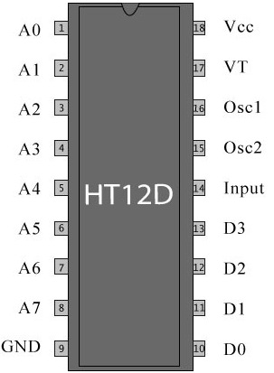
    2.)Encoder(HT12E IC):- It decodes the data is received by the RF receiver module.The input data is decoded when no error or unmatched codes are found. A valid  transmission in indicated by a high signal at VT pin that is pin no 17.
    HT12D
    • pin 18     : It is use to give the +vcc or biasing to the  IC HT12D this pin is connected with the +5 volt
    • Pin 17     : It is the valid transmission pin it will high when the transmission is ok so that we connected this pin to an led for indication.
    • Pin 16-15: we connect these two pin directly by a 51k resistor
    • Pin 14     : This pin is connected with the rf receiver module data pin to receiving the serial data.
    • Pin 10-13: These pins are data pin which is transferred by the Transmitter module.

    3.)ARDUINO Board : Arduino is an open-source platform based on avr (atmega series). It’s a combination of easy to use software and hardware environment for electronics student, developer, hobbyists to create interactive devices and environments.
    Arduino can be easily interfaced with sensors, controlling led’s , motor driving, relays. The on board  microcontroller is programmed with help of arduino programming language, and arduino development environment.

    4.)Computer : Finally the Computer get the data  from the Arduino board and act according to the program one appliationis also need to connect the port to ppt.

    Here is the full setup of receiver module.


    Software Section:
    *******************************************************************************
    ARDUINO PROGRAM written in arduino ide.
    *******************************************************************************
    int left_sense=9;    // left sensor pin
    int right_sense=8;   // right sensor pin

    void setup()
    {
      Serial.begin(9600);
      pinMode(left_sense,INPUT);
      pinMode(right_sense,INPUT);
    }

    void loop()
    {
      while(1)
      {
        int left_data = digitalRead(left_sense);    //reading left sensor data
        int right_data = digitalRead(right_sense);  //reading right sensor data
        while(left_data == 1)                       //hand on left sensor 
        {
          left_data = digitalRead(left_sense);
          right_data = digitalRead(right_sense);
          if(right_data == 1)                      // passng through right sensor
          {
            Serial.println("D");
            while(right_data == 1)                // wait to over the swipe
            {
              right_data=digitalRead(right_sense);
            }
          }
        }
        while(right_data == 1)
        {
          left_data = digitalRead(left_sense);
          right_data = digitalRead(right_sense);
          if(left_data == 1)
          {
            Serial.println("B");
            while(left_data == 1)
            {
              left_data = digitalRead(left_sensor);
            }
          }
        }
      }
    }
          
    *******************************************************************************

    *******************************************************************************
     PC AAPLICATION TO CONTROL PPT.
    For downloading the PC application to connect your hardware to PC please CLICK HERE

    *******************************************************************************


    POWERPOINT CONTROL USING GESTURE

     
    2embeddedrobotics © 2015 - Designed by Templateism.com