Proteus (ISIS Design) tool is very popular platform for simulating an electronic design before making its real hardware but its hard to get every components and its functionality in proteus. So we interface hardware components with proteus design like RFID Module, GSM Module, Bluetooth Module, Finger Print Module etc. via virtual serial port emulation( VSPE) software.

Virtual Serial Port Emulation (VSPE): VSPE is use to help developers to create applications that use serial ports. It is able to create various virtual devices to transmit/receive data. One Serial port can be opened into many different applications and use their different functionality. With VSPE you are able to share physical serial port data for several applications, create virtual serial port device pairs and so on.
DOWNLOAD VSPE : Click Here
DOWNLOAD VSPE : Click Here
Configuring VSPE: Step by Step process to configure the VSPE shown below.
1) Open the VSPE from my program or by desktop icon.

2) Now go to the Device>Create after clicking the Create below window open.

3) Now specify device type and select splitter and click on Next button

4) Now Plug the USB2Serial into the USB Port and open the Device Manager and check for the Port number (ex: COM4).
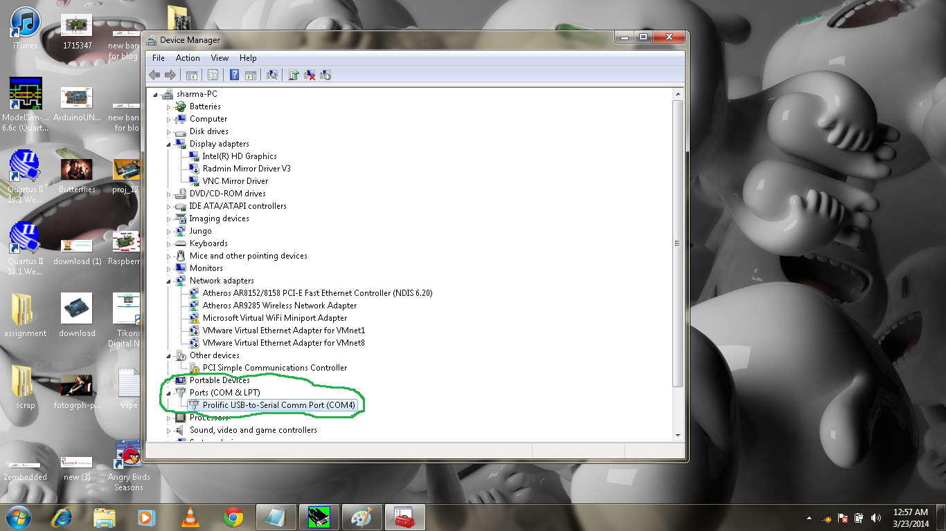
5) Now check the VSPE window back and specify device characteristics. Now their are two blocks
- Virtual Serial Port > specify the number you want to give the virtual port you want to make (ex com1)
- Data Source Serial Port > In this field put your COM Port number which you get into the last step. COM4.

6) Now left Click on Settings.. and select 9600 in speed field.where 9600 is the baud rate of communication. Now left Click on Finish button.

7) After Clicking on Finish button the virtual device will initialized.

The Virtual Device finally Configured now we Need to configure the proteus (ISIS Design).
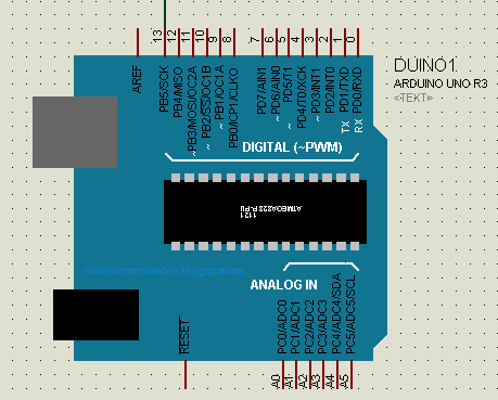
COMPIM: The COMPIM model is a Physical Interface Model of a serial
port. Incoming serial data is buffered and presented to the circuit as a
digital signal, whilst serial digital data generated by a CPU or UART model appears at the PC's physical COM
port. The COMPIM model also provides for baud rate translation, and for
optional hardware or software handshaking on both the physical and virtual
sides of the device.
1) Add the COMPIM in ISIS from its component mode.


2) Now Add the Virtual Terminal from the Virtual instrument mode.
connect the RXD and TXD of virtual terminal to RXD/TXD to COMPIM.

3) Now right click on COMPIM and select the Edit Properties.

4) Change the Baud rate of physical port and virtual port to 9600 as shown in the fig below.

Do the same step for virtual terminal.

5) now press the Play button as in the fig below


6) Now punch the card and see the data at virtual terminal in the fig below as i mentioned already that i used the RFID Module for this tutorial as an example.


I hope the above post would help you. I really welcome your suggestions and queries.
****************
THANK YOU
****************

Serial Devices Interfacing to Proteus Using VSPE
22:44