Sunday 30 October 2011


Writing a c program for mobile operated robot is not a very difficult task we just have to take the basic block diagram in our mind that a microcontroller get the input and give the decision based on our program.
Now form the DTMF decoder we will get the 4 bit data on the port2 of microcontroller 8051.We also know that the data given by decoder is equal to a number pressed by input mobile.

HARDWARE CONFIGURATION: Before writing the program we should know the hardware configuration of the circuit where the input's and output's are connected and for what task we have to make the program.
INPUT'S: The microcontroller 8051 is connected with DTMF decoder as follow -the port 1 is the input port where the DTMF data bits  D0 to D3 are connected with P1.0 to P1.3 as given in the below fig.
DTMF &  MICROCONTROLLER  CONNECTION 
**Note:-for making the port1 as an input port pass 0xff at the port1.

OUTPUT'S: The microcontroller 8051 is connected with motor driver as follow: the port 2 is the output port and the pin connection is shown in fig. for moving the motor's in forward direction we have to give 10 to the motor or (M1A =0  & M1B =1) this condition makes the motor M1 in forward direction.

MOTOR DRIVER & MICROCONTROLLER CONNECTION
**Note:-for making the port2 as an output port pass 0x00 at the port2.
CREATING LOGIC:  Now the main part of the programming  is to create a decision on the basis of some condition like when the key 2 is press then send some data to the output prot of the  microntroller now I create  a data according to my project you can create your own.I am using the key 2,4,6,8 & 5 for controlling the robot.
DECISION BASED ON CONDITION
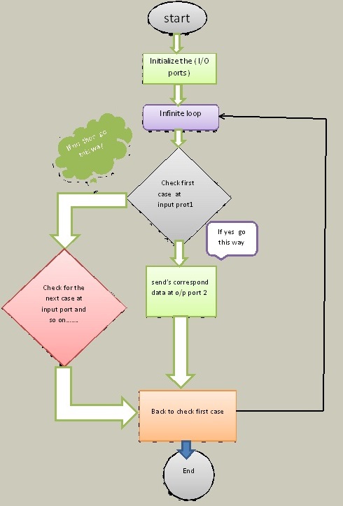
FLOW CHART: Programming is an art which includes some step's the flow chart is also a step of programming we can make the program without a flow chart but for making an efficient and error free program then we should use this step a flow chart of the program is shown below.

C PROGRAM FOR MOBILE OPERATED ROBOT:

****---------------------------------------------------------------------------------------------------------------------****

#include<reg51.h> //header file for 8051 microcontroller
void Main()
{
P1=0xff; //initialize as an input port
P2=0x00; //initialize as an output port
while(1) //infinte loop
   {
     if(P1==0xf2) //check for key 2-decision is forward
        {
          P2=0x0a; //m1 and m2 forward as 1010 these are four lsb bits of port 2
        }
      else if(P1==0xf4) //check for key 4-decision is left
         {
           P2=0x08;
        }
       else if(P1==0xf6) //check for key 6-decision is right
        {
            P2=0x02;
      }
      else if(P1==0xf8) //check for key 8-decision is backward
       {
           P2=0x05;
       }
      else if(P1==0xf5) //check for key 5-decision is stop
      {
           P2=0x00;
     }
    else
           P2=0x00;
    }
}

****--------------------------------------------------------------------------------------------------------------------****


mobile operated robot program

MOBILE OPERATED ROBOT: The robot is made for the purpose military operation, spy robot or navigator in forest.The mobile operated robot is a very small application of DTMF technology we showing you how we can use the DTMF to operate a robot  because the robot is operated by a mobile so the range of the robot communication is not limited its just depends on the network of the mobile and in present senario the mobile network is everywhere.
DTMF KEYPAD
DTMF: DTMF(Dual Tone Multi-Frequency) , better known as touch-tone is a system of signal tones in telecommunications.This technology is used in several of Applications for example voice mail, customer care,telephone banking etc.
There are twelve DTMF signals, each of which is made up of two tones from the following selection.
ROW'S- 697 Hz ,770 Hz ,852 Hz, 941 Hz.
COLUMN'S- 1209 Hz, 1336 Hz, 1447 Hz , 1633 Hz.
The tones are divided into two groups (low and high) , and each DTMF signal uses one of tone from each group. This prevents any harmonics from being misinterpreted as part of the signal.


DTMF DECODER PIN OUT
DTMF Decoder: The DTMF tone is decoded by the DTMF Decoder ic that is HT9170 which decoded a dtmf tone and gives a four bit data at the output of the decoder.Now this four bit data can be use  for  making the decision as for the key pressed on the mobile keypad the data have different for a different key.some important pin of HT9170 are listed below:-
1. Pin 15(DV data valid): The data valid pin is become high when the dtmf decoder receive a valid data or this pin hold's the 5v when the key is pressed.
2. Pin 10(OE output enable): This pin is use to enable the output when this pin is high the data pin are active and the decoded output is sent to the decoded pin.
3. Pin 11-14(D0-D3 data pins): These are the data pins which makes the 4 bit data after pressing a key on the mobile such as 0001 for pressing the key 1 and other are shown into the picture shown.
4. Pin X1 or X2: These pin's are use for providing the oscillation to the ic basically a xtal of 3.579 MHz is used here. for more details download the HT9170 datasheet .DOWNLOAD 

SOFTWARE:  For the program of this circuit click here 

CIRCUIT: The circuit is made in different modules

1.Power supply : For power supply just click here 
DTMF DATA OUTPUT

2.Input or DTMF decoder:
DTMF Application circuit


3.Decision (microcontroller 8051): For 8051 microcontroller circuit just click here  

4. Motor driver circuit:  The IC-l293d  is well known as motor driver this is 12v motor driver we use the motor driver IC because our micro-controller is work on 5v and the motor have different operating voltage. So to meet with these parameter we use these driver IC there are so many other IC available for different configuration.


The full circuit for mobile operated robot is as follow :

back & front view of circuit
robot


final robot


Mobile Operated robot(DTMF Tech.)

Thursday 13 October 2011

All the student's may not properly works on microcontroller because  shortage of programmer kit(burner kit) whatever the  problem they have ,so now you can make your own programmer kit for 8051 microcontroller and can make more practical application and learn more efficiently in this field.For making the programmer kit we make the circuit step by step.
FOR P89V51RD2 microcontroller
Power Supply
  • Power supply 
  • DB9 connector
  • Line driver circuit
  • 8051 
  • final circuit of Programmer kit
1.  POWER SUPPLY: Before making any circuit we need to design its power supply it consist of many part like step down, ac-dc conversion, voltage stabilizing etc but we will giving the power to our board from an 12-volt adapter so our power supply consist of a voltage regulator,capacitor,diode, led and connector. 
    7805 voltage regulator
    • 7805:-It is the voltage regulator ic as pin diagram is shown.
    • diode IN4007 and the silver line part is its negative.
    • resistor R1=330ohm or we can also use 470ohm because it is use with the led.
    • A 2 pin male connector is required for giving the power to the circuit the +ve will connect with 1 pin of 7805.
    • A 1000uf capacitor is also use with power supply to reducing the ripple or maintaining the continuity.
    • Led:-the cutted portion of the led is negative.
2.  DB9 CONNECTOR: DB9 connector is use to connect the computer with your  programmer board it uses the RS232 cable to connect the DB9 port has 9 pins each pin has its own function but we will use only pin no 2 , 3 and  5.
  • pin no 2 is known as recieved data bit when controller transmit the data bit then computer recive from this pin. This is connected to the 14th pin of max232.
  • pin no 3 is named as transmit data the data will transmit form the computer with the help of this pin and this is connected 13th pin of max232.
  • pin no 5 we make this pin normally ground.
3.  LINE DRIVER CIRCUIT: The MAX232 is an Integrated Circuit that convert signal from an RS232 serial port to signal suitable for use in ttl compaitable digital logic circuits.The MAX232 is a dual driver/receiver and typically converts the RX, TX, CTS and RTS signals.For more details of MAX232 you can download the datasheet of it form here. download  
  • here the values of all the capacitors are 0.1 uf.
  • 16 pin is vcc should be maintained at 5volt dc.
  • the 15th pin becomes ground.
  • T1out-pin is use to send the data serially to the computer.
  • R1in-pin is use to recieve the data from the computer serially.
  • T1in-pin is use to tramsmitt the data from microcontroller to MAX232 which is actually going to computer.
  • R1out-pin is use for send the incoming data from MAX232 to microcontroller which is actually come from computer.
  • Download the MAX232 datasheet here.download 
4.  8051: The basic 8051 circuit consist of reset circuitry and oscillator circuit but before this we will look the pin diagram of the 8051 that how or what pin's we are using to make our circuit.
8051 microcontroller

As we can see in the fig next that the 8051 microcontroller has 40 pin it has 32 pin I/O lines or we can 32 input and output lines .It consist of four 8bit port's thats why we call it 8bit microcontroller. For our circuit we only need 8 pins these are as follow.
  • We need a 40 pin IC base
  • RST this is the pin  no 9 called as reset pin this pin reset the program counter 0f 8051 microcontroller and it is active high.
  • XTAL1 and XTAL2 are for providing the oscillations to the controller.
  • 10 and 11th pin are use for serial communication.
  • 40th and 31st is to provide vcc basically set at 5volt.
  • 20th pin is become ground.
*The two basic circuit for 8051 microcontroller are listed below.
reset circuit
XTAL connection to8051
4.  FINAL PROGRAMMER CIRCUIT: When we connect the all small circuit with each other than the programmer circuit is in front of you and it is like below.

8051 programmer kit

Wednesday 12 October 2011

Before starting to learn 8051 microcontroller we need an initial setup like an environment in which we have basic requirement to learn 8051 like programmer board to program a microcontroller,simulator to write our codes,driver support the hardware etc.So here are some short of steps you have to follow to prepare your computer for 8051.
  1. Install the KeilUvision3 software in your system if you do not have the keil then dont worry you can download it from here Download
  2. Now install the serial to usb driver in your system if you are using a serial to usb cable well it is come with your serial cable driver cd but if you don't have then download.
  3. After this you are able to write your codes in C and assembly languages and can check your codes are working or not by your simulator.
  4. Now for transferring those codes into the microcontroller Install Flash magic in your computer or download it form here download.
  5. Buy an 8051 Development board it may cost you around 800 rupee and also a microcontroller of nxp  series p89v51rd2.
  6. you can also make your own programmer kit for 8051 microcontroller. programmer kit 
  7. Now you have all necessary things to learn 8051 lets start if having any doubt or facing any problem then can contact me on my mail id.
                                                           @BEST OF LUCK@

Initial setup

Friday 7 October 2011

EMBEDDED SYSTEM: In general ,"embedded system "is not a definable term as most systems have some element of extensible or programmability but we can say that An Embedded System is a combination of some electronics components , software , mechanical hardware to perform a specific task at a particular instance of time.Embedded system  capture application area like industry,medical,construction,transportation etc.The embedded system is every where near us whether it is industry or our daily life.

  1. SPECIFIC TASK: An Embedded system is design for a specific task if it is not only for a single task than it is not an Embedded system.Some people think that computer is an embedded system but they all are wrong because the computer is not an Embedded system it is combination of embedded system as it does so many task  at same time.some example of Embedded system are Led message display, Ac,Abs(anti breaking system) in car .
  2. ELECTRONICS CIRCUIT: Electronics circuit in an embedded system is to make the system live.It is the heart of the embedded system. It basically fetch the data from the environment in the form of sound , visual , light etc and then convert it into the voltage or current and then process by the decision making device like microcontroller or microprocessor and make a decision on the basis of input data. In this sensor's are use to sense the environment or actuator's are use to perform a an action may be motion .
    • SENSOR'S: The sensor;s in the embedded system are like the eyes,ear,nose or skin for a human body they are use to fetch the data .for example eyes of a human being are use to see the visual like as a camera is use to see the visual for a robpot or in the embeddded system this is what we called a sensor.Their is a variety of sensor's like co2 sensor,joystick, IR sensor, Ultrasonic etc.
    • DECISION TAKING DEVICE(microprocessor or controller): This is the brain of a robot or embedded system like our nose sense the smell of the food then our brain take the decision that the food is fresh or not same as in the embedded system the microcontroller or the microprocessor take the decision that wether the task should be performed or not.
    • ACTUATOR'S: Actuator's are that part of the system which perform the task finally it can be a motion or flashing a light.If we compare it with the human then it is like our hand that automatically become in motion if someone behave very bad. A best example of the actuator is the motor's which is use to give the motion.
3.   SOFTWARE: The software is a very important part of the embedded system.It is stored in the memory of the system and basically provide the computational capability to the system.software is run by the micro-controller or microprocessor.Software is the set of instruction to perform  task on the basis of some logic.It is written in the computer language may be in the C language or in Assembly depends on the requirement of the    system and also on the basis of complexity of the logic.

4.  MECHANICAL  HARDWARE: The mechanical hardware is the body of the system.It is the structure of the system like bones in the human body for example in the robots the wheel's , chasis ,belt , gear  etc are the mechanical hardware which is responsible for conversion of motion to some action like walking using some motor's the best live example of mechanical hardware in embedded system and robotic is the asimo robot.

Embedded System

 
2embeddedrobotics © 2015 - Designed by Templateism.com