
 A Ball follower robot is a very good application of embedded system and robotic. A new embedded student can make this intelligent robot. Starters was not trying to make the ball follower robot because they think that they need to use a camera for following the ball.this robot use some IR pair to sense the ball instead of camera so you do not need to learn digital image processing.
Now break the task in three different module as per the definition of an embedded system.
 |
| ball following concept |
- Sensor module: IR sensor, lm324 etc
- Decision module: p89v51rd2(8051 mc)
- Actuator module: L293d(motor driver) , motors etc
 |
| IR sensor principle |
SENSOR: Well I chose three IR sensor for sensing a ball and bases on that i can make the decision where to move or in oter words we can follow a ball. IR sensor works on the reflection concept when an Infra-red beam is transmit towards an object it should get reflected by that object and that's how we can recognize the ball.
 |
| IR circuit |
 |
| IR Sensor |
Now the circuit as we can see in the IR circuit that this circuit gives the high voltage output when the less Infra-red rays get reflected back and a low voltage when high reflection of rays occur. For transmitting we have an IR led which work in forward bias condition and at the reception point we use an IR receiver to accept the IR rays and changes the analog voltages according to that.
 |
| comparator |
From the IR sensor we get the analog data so we have to change that in the digital format like when an object seen than it should return 0v or 4v or in other word's we can say that in high or low voltages because we kno that in digital high voltage = 1 and low voltage= 0.
 |
| comparator data |
For the purpose to change the analog voltage into digital we use comparator which compare the analog voltage to a reference voltage and give a high or low voltage a desired for controller.
 |
| lm324 comparator ic |
The figure shown here is a comparator IC the pin 1,7,8 and 14 are use to give out put to the micro controller. we should connect a reference voltage to the -ve terminal of this IC lm324 and the out put of the IR sensor to its +ve terminal's.
The circuit show below is for your sensor module this is nothing just the summer of what we discuss in sensor subtopic.
 |
| IR sensor with comparator circuit |
PROCESSING: The processing is the most important part of the robot. Till now we get the data from the sensor now based on that data we have to make some decision so here the role of micro controller is come up. we use an 8051 micro controller for our circuit to give them a decision capability. Our micro controller is made by nxp the product name is P89V51RD2. The basic circuit to initialize the micro controller is shown below. we just need an reset circuit and oscillator and bias the controller.
 |
| 8051 micro controller circuit |
we use the port 1 as an input port and port 2 as an output port.
so the sensor will connect with pin 1,2,3 and motor should be connect with pin 21,22,23,24.
Now let check how actually we making our decision or our robot how to sense where is the ball and where we have to move.
|
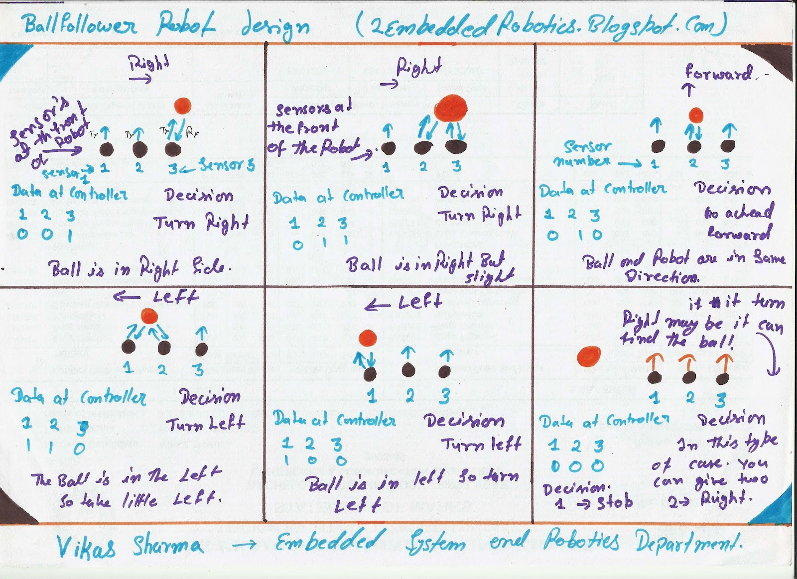
| decision making |
we can see in above figure that sensor 1,sensor2, sensor 3 are three sensor's which gives us a digital data(001,110,010 etc). On the basis of this data we make our decision let us look an example of first figure the robot have to move towards right direction because ball is in right direction. We sense it by our sensor as sensor 1 and sensor 2 will not get reflection of ray so they probably gives 0 to micro controller.
ACTUATOR'S: The Actuator's are those devices which actually gives the movement or to do a task like motor's but their are various types of motor's in the market which works on different voltages. So we need motor driver for running them through the controller. To get interface between motor and micro controller. We use the l293d motor driver IC in our circuit.
 |
| motor driver circuit |
As in above circuit a 2 pin male connector in connected to the pin 8 this will provide the operating voltage for the motor like if we want to run our voltage on 12volt. so we just have to connect a 12volt power source to this 2 pin male connector.
COMPLETE CIRCUIT OF THE BALL FOLLOWER ROBOT: When we connect all of our module in a sequential way then we can get our complete circuit of the ball follower robot first sensor module and then decision module and in last motor driver.
 |
| complete circuit of ball follower robot using IR sensor |
VIDEO OF THE BALL FOLLOWER ROBOT USING IR SENSOR: After making this robot i make a video to give the evidence of the robot.
IMAGES OF THE ROBOT:


***************************than you ********************************
ball follower robot( IR Sensor)
17:44

.jpg)


