Showing posts with label Arduino. Show all posts

Tuesday, 7 October 2014

In this Artical we will see how to establish communication between computer/mobile to Arduino in a LAN or Wireless Network. We are interfacing the ENC28J60 Ethernet controller to Arduino so that our Arduino will be the one of member of that network. Once it will done the arduino can control things in that network or the arduino can be controlled by the other devices of that network it might be computer or mobile. Interfacing Arduino with the ENC28J60 will further gives us the freedom of using the internet on Arduino but before that we need to learn how to do all that networking stuff in a locan network.

Soon I will post about how to control the things in local network, how to send data on a local network, and how to interfaced with Android devices or how to make IOT Devices. IOT Devices are quite famous.
 

A simple block diagram of the data flow  is in the image below.


Ethernet Module( ENC28J60):  Microchip's ENC28J60 is a 28-pin,  Ethernet Controller with on board MAC & PHY, 8 Kbytes of Buffer RAM and an SPI serial interface. With a small foot print package size the ENC28J60 minimizes complexity, board space and cost. It used in so many application like Industrial Automation, Building Automation, Home Control, Security and Instrumentation, IOT Devices.
You can build Your own circuit but I use the Module to save my time.


VIRTUAL SIMULATION: I first simulate my design on the Proteus ISIS to make sure I am working in right direction and also to save my time. In ISIS their is already a component named "ENC28J60 ethernet controller" so I picked it from the library. Now I picked up the Arduino and connect it with the ethernet controller.


if the link dont work please comment

* Connections:   
  
Now make these connection in the ISIS design tool.


SOFTWARE: Now we all done with the Virtual Hardware Design lets make the software. All you need is the Ethercard Library for this example. Download it from here EtherCard. Click here
  • Extract the ZIP file , copy and paste the folder in your Arduino1.xx/library/  
  • once you place the folder in your arduino library folder restart your Arduino IDE
  • Now  go to ethercard > Examples > backsoon
 
 Compile the code  : if facing any problem then go to :  How To Simulate Arduino in ISIS

Make some changes in the program as given below
changes are in Red colour
Arduino code
/*#############################################################################
###############################################################################*/

// Present a "Will be back soon web page", as stand-in webserver.
// 2011-01-30 <jc@wippler.nl> http://opensource.org/licenses/mit-license.php

#include <EtherCard.h>

#define STATIC 0  // set to 1 to disable DHCP (adjust myip/gwip values below)

#if STATIC
// ethernet interface ip address
static byte myip[] = { 192,168,1,200 };
// gateway ip address
static byte gwip[] = { 192,168,1,1 };
#endif

// ethernet mac address - must be unique on your network
static byte mymac[] = { 0x74,0x69,0x69,0x2D,0x30,0x31 };

byte Ethernet::buffer[500]; // tcp/ip send and receive buffer

// char page[] is the HTML page you are uploading ..
char page[] PROGMEM =
"HTTP/1.0 503 My Seriavice \r\n"
"Content-Type: text/html\r\n"
"Retry-After: 600\r\n"
"\r\n"
"<html>"
  "<head><title>"
    "2embeddedrobotics "
  "</title></head>"
  "<body>"
    "<h3>Welcome to 2embeddedrobotics</h3>"
    "<p><em>"
      "The World of IOT Devices .<br />"
      "yipeee   Congrats...."
    "</em></p>"

   "</body>"
"</html>"
;

void setup(){
  Serial.begin(9600);
  Serial.println("\n[backSoon]");
 
  if (ether.begin(sizeof Ethernet::buffer, mymac) == 0)
    Serial.println( "Failed to access Ethernet controller");
#if STATIC
  ether.staticSetup(myip, gwip);
#else
  if (!ether.dhcpSetup())
    Serial.println("DHCP failed");
#endif

  ether.printIp("IP:  ", ether.myip);
  ether.printIp("GW:  ", ether.gwip); 
  ether.printIp("DNS: ", ether.dnsip); 
}

void loop(){
  // wait for an incoming TCP packet, but ignore its contents
  if (ether.packetLoop(ether.packetReceive())) {
    memcpy_P(ether.tcpOffset(), page, sizeof page);
    ether.httpServerReply(sizeof page - 1);
  }
}
/*##############################################################################
###############################################################################*/

now compile the code with prefrence compile. in file option.. so that you will get the .HEX file for ISIS.


Now you have done every thing . Hit the Play Button and it will give you the assigned IP address in serial monitor now write it down on a paper.

 
open the web browser and write the IP address of your arduino in the browser.
 

 Now you can watch this page on any device connected to that network  As I show.

HARDWARE: We already did everything in virtual now we just need to connet each component as per the connection given in starting.
Now upload the program to your Arduino and turn on its Serial monitor so that u can get Your 
"IP in Serial Monitor" and just open browser and put your IP and check the webpage.


Now you have done then note your IP from the serial monitor and Enjoy..
Wish you a very good Luck.


Ethernet(ENC28J60) Interfaced Arduino

Monday, 24 March 2014

Proteus (ISIS Design) tool is very popular platform for simulating an electronic design before making its real hardware but its hard to get every components and its functionality in proteus. So we  interface hardware components  with proteus design like RFID Module, GSM Module, Bluetooth Module, Finger Print Module etc. via virtual serial port emulation( VSPE) software.


Virtual Serial Port Emulation (VSPE): VSPE is use to help developers to create applications that use serial ports. It is able to create various virtual devices to  transmit/receive data. One Serial port can be opened into many different applications and use their different functionality. With VSPE you are able to share physical serial port data for several applications, create virtual serial port device  pairs and so on.

DOWNLOAD VSPE : Click Here

Configuring VSPE: Step by Step process to configure the VSPE shown below.

1) Open the VSPE from my program or by desktop icon.


2) Now go to the Device>Create after clicking the Create below window open.


3)  Now specify device type and select splitter and click on Next button


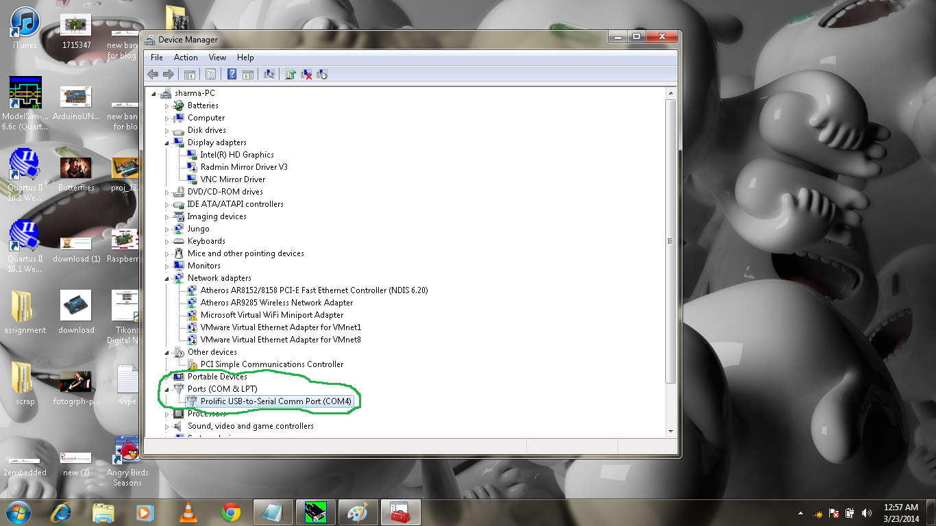
4) Now Plug the USB2Serial into the USB Port and open the Device Manager and check for the Port number (ex: COM4).


5) Now check the VSPE window back and specify device characteristics. Now their are two blocks 
  • Virtual Serial Port > specify the number you want to give the virtual port you want to make (ex com1)
  • Data Source Serial Port > In this field put your COM Port number which you get into the last step. COM4.

6) Now left Click on Settings.. and select 9600 in speed field.where 9600 is the baud rate of communication. Now left Click on Finish button.


7) After Clicking  on Finish button the virtual device will initialized.


The Virtual Device finally Configured now we Need to configure the proteus (ISIS Design).

COMPIM: The COMPIM model is a Physical Interface Model of a serial port. Incoming serial data is buffered and presented to the circuit as a digital signal, whilst serial digital data generated by a CPU or  UART model appears at the PC's physical COM port. The COMPIM model also provides for baud rate translation, and for optional hardware or software handshaking on both the physical and virtual sides of the device.

1) Add the COMPIM in ISIS from its component mode.


2) Now Add the Virtual Terminal from the Virtual instrument mode.
   connect the RXD and TXD of virtual terminal to RXD/TXD to COMPIM.


3)  Now right click on COMPIM and select the Edit Properties.


4) Change the Baud rate of physical port and virtual port to 9600 as shown in the fig below.


Do the same step for virtual terminal.


5) now press the Play button as in the fig below


6)  Now punch the card and see the data at virtual terminal in the fig below  as i mentioned already that i used the RFID Module for this tutorial as an example.


I hope the above post would help you. I really welcome your suggestions and queries.
****************
THANK YOU
****************


Serial Devices Interfacing to Proteus Using VSPE

Tuesday, 4 March 2014

ISIS design environment helps an embedded system developer from the painful electronic verification of the circuits. It became the first choice for electronics engineer to verify its design and simulate it in real-time environment before making it real hardware. It reduces the design time and cost also. 

In this article we will see how to simulate an Embedded System design with ARDUINO UNO Board having ATMEGA328 microcontroller. Engineers who are frequently using the Arduino for their application would know that how to blink LED in arduino.


ADDING LIBRARY TO ISIS: 
  • Download the Library from here.  click here
  • Now extract the ARDUINOLIBS,zip and open the folder copy ARDUINO.LIB and ARDUINO.IDX files
  • Now paste these 2 files into library folder which could be located at "C:\Program Files\LabcenterElectronics\LIBRARY\" in your system
  • once you paste your file its over for ISIS.
MAKING DESIGN IN ISIS:
  • Open ISIS software then goto component mode and click P(pick from library) 
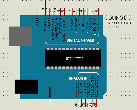
  • write arduino and select and click into the workspace and connect an LED to pin 13 of arduino 
WRITING PROGRAM:
  • Open ArduinoIDE and open the blink project
  • Goto: file->prefrences->compilation   check that box
step by step process in images>>


* Now click on verify button or go to sketch and verify


* Now note the address of the location of hex file generated by arduino. which is in blue color circle.


DUMPING HEX FILE INTO BOARD:
Now open the ISIS design again and double click on ARDUINO image in ISIS design.
Now give the path in the field shown below in orange color circle.


now press ok and hit the run button to play the simulation and enjoy :-)

Download Project:  click to download project. click here

ARDUINO SIMULATION USING PROTEUS( ISIS )

Friday, 31 May 2013


MS PowerPoint is very important part of our professional and student life .we face several  problems  while giving the presentation or seminar on some topic like we need an operator to operate the slides and sometimes this will create problems if speaker and operator are not well prepared. To overcome this problem we made the gesture device which can be connected to the computer and operated by the speaker gesture.


The device basically have two part gesture transmitter and computer receiver.


In this device we first recognize the direction of right hand  movement by placing ir sensor on left hand. Then the data is transmitted by the transmitter and the receiver receive the data and give to the computer and one application in  the computer control the ppt. You can download that application here.DOWNLOAD APPLICATION.

HERE IS THE DEMO VIDEO OF THE APPLICATION...


GESTURE TRANSMITTER MODULE: The gesture transmitter Module consist of four different part.
1. IR Sensor Pair
2. LM324 OP-Amp IC.
3. HT12E Encoder IC.
4. RF Transmitter Module


IR sensor principle
As given in block diagram of Gesture transmitter module the IR sensor pair give the data to LM324 which compare the voltage of the IR pair output to the reference voltage and make it to digital. This digital data is further going into the HT12E encoded and transmitted by the Rf transmitter module.

SENSOR: Well I chose two IR sensor for sensing the hand movement on left or right side.on sensig data i can make the decision where to move my power point slide. IR sensor works on the reflection concept when an Infra-red beam is transmit towards an object it should get reflected by that object and that's how we can recognize the hand movement.


IR circuit

Now the circuit  as we can see in the IR circuit that this circuit gives the high voltage output when the less Infra-red rays get reflected back and a low voltage when high reflection of rays occur. For transmitting we have an IR led which work in forward bias condition and at the reception point we use an IR receiver to accept the IR rays and changes the analog voltages according to that.
comparator
From the IR sensor we get the analog data so we have to change that in the digital format like when an object seen than it should return 0v or 4v or in other word's we can say that in high or low voltages because we kno that in digital high voltage = 1 and low voltage= 0. 
comparator data
For the purpose to change the analog voltage into digital we use comparator which compare the analog  voltage to a reference voltage and give a high or low voltage a desired for controller. 
lm324 comparator ic

 The figure shown here is a comparator IC the pin 1,7,8 and 14 are use to give out put to the micro controller. we should connect a reference voltage to the -ve terminal of this IC lm324 and the out put of the IR sensor to its +ve terminal's.
The circuit show below is for your sensor module this is nothing just the summer of what we discuss in sensor subtopic.
IR sensor with comparator circuit


HT12D
ENCODER(HT12E IC): The HT12E is an 4bit encoder which encode the input data applied on it .The pin description of the HT12E is shown in the figure .
  • pin (1 to 8) A0-A7 known as address bits so we do not need to consider them.
  • pin no (9 and 18) are use to bias the IC  as pin-18 as VCC and pin-9 as GND.
  • pin - 17 is connected to the rf transmitter module Din.
    • pin-16 and pin-15 are connected by an Osc resistor known as Roscc(1.1 Mohm)
    • pin-14 is connected to ground to enable the transmitt.
    • pin-13 to pin-10 are known as AD0 to AD3 those having the 4bit data which is required to transmit.
    RF TRANSMITTER MODULE(TX):  .The transmitter module is working  on the frequency of 433MHz and is easily available in the market at the cost of 250rs .
    RF Transmitter module
    • The vcc pin is connected to the +terminal in the circuit.
    • The data pin is connected to the HT12E(pin no-17) that is transmitted or we can say that encoded data.
    • The next pin is shown in figure is GND that is connected to the ground terminal.
    • Now the last pin ANT this is connected to a small wire as an antenna.

    Final circuit setup


    COMPUTER RECEIVER MODULE: The Computer Receiver module consist different parts.

    receier module
    As shown in the block diagram RF receiver module get the transmitted signal sended by transmitter and then HT12D decodes that data in four bit digit and given to the ARDUINO board for making an decesion and send to computer via serially. One application is running in the computer which understand the signal sended by Arduino and control the PPT slides while presenting

    Hardware Part: - 1.) Computer
                                 2.) ARDUINO BOARD
                                 3.) HT12D decoder IC
                                 4.) RF Receiver module

    1.) RF Receiver Module : The RF receiver module will receive the data which is transfered by the Transmitter module. It is also working as similar to the transmitter module-
    • Connect the +vcc pin to the 5volt terminal
    • Connect the ground pin to the ground terminal 
    • The data pin is then connected to the HT12D (pin-14)
    • So that we can get the decoded 4 bit data


    2.)Encoder(HT12E IC):- It decodes the data is received by the RF receiver module.The input data is decoded when no error or unmatched codes are found. A valid  transmission in indicated by a high signal at VT pin that is pin no 17.
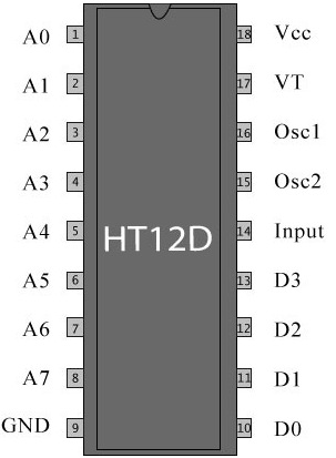
    HT12D
    • pin 18     : It is use to give the +vcc or biasing to the  IC HT12D this pin is connected with the +5 volt
    • Pin 17     : It is the valid transmission pin it will high when the transmission is ok so that we connected this pin to an led for indication.
    • Pin 16-15: we connect these two pin directly by a 51k resistor
    • Pin 14     : This pin is connected with the rf receiver module data pin to receiving the serial data.
    • Pin 10-13: These pins are data pin which is transferred by the Transmitter module.

    3.)ARDUINO Board : Arduino is an open-source platform based on avr (atmega series). It’s a combination of easy to use software and hardware environment for electronics student, developer, hobbyists to create interactive devices and environments.
    Arduino can be easily interfaced with sensors, controlling led’s , motor driving, relays. The on board  microcontroller is programmed with help of arduino programming language, and arduino development environment.

    4.)Computer : Finally the Computer get the data  from the Arduino board and act according to the program one appliationis also need to connect the port to ppt.

    Here is the full setup of receiver module.


    Software Section:
    *******************************************************************************
    ARDUINO PROGRAM written in arduino ide.
    *******************************************************************************
    int left_sense=9;    // left sensor pin
    int right_sense=8;   // right sensor pin

    void setup()
    {
      Serial.begin(9600);
      pinMode(left_sense,INPUT);
      pinMode(right_sense,INPUT);
    }

    void loop()
    {
      while(1)
      {
        int left_data = digitalRead(left_sense);    //reading left sensor data
        int right_data = digitalRead(right_sense);  //reading right sensor data
        while(left_data == 1)                       //hand on left sensor 
        {
          left_data = digitalRead(left_sense);
          right_data = digitalRead(right_sense);
          if(right_data == 1)                      // passng through right sensor
          {
            Serial.println("D");
            while(right_data == 1)                // wait to over the swipe
            {
              right_data=digitalRead(right_sense);
            }
          }
        }
        while(right_data == 1)
        {
          left_data = digitalRead(left_sense);
          right_data = digitalRead(right_sense);
          if(left_data == 1)
          {
            Serial.println("B");
            while(left_data == 1)
            {
              left_data = digitalRead(left_sensor);
            }
          }
        }
      }
    }
          
    *******************************************************************************

    *******************************************************************************
     PC AAPLICATION TO CONTROL PPT.
    For downloading the PC application to connect your hardware to PC please CLICK HERE

    *******************************************************************************


    POWERPOINT CONTROL USING GESTURE

     
    2embeddedrobotics © 2015 - Designed by Templateism.com