
We make this project to control the appliances installed in our home or industry via remote. we use a RF Transmitter / Reciever for exchanging the bits to turn on or off the devices in a particular range (typically10-100 meters). The figure of remote controlled home automation shows how the devices are turn off and on. Basically a receiver circuit is installed in our home this circuit is connected to the devices by the relay(electromechanical switch).
 |
| Remote controlled home automation |
The major components to implement a remote are:-
- RF Transmitter module
- HT12E(4bit encoder)
- power supply
- PUSH button circuit
The major components use to make receiver box are:-
- RF Receiver module
- HT12D(4bit decoder)
- power supply
- controller circuit
- relay circuit
REMOTE: The remote for our system is consist of several component as listed above the RF Transmitter module is connected to the encoder ic output. The encoder(HT12E) encode a four bit data into a single bit that is Dout which is get into the RF transmitter module and the transmitter module transmit it into the particular area.
**RF Transmitter Module: The transmitter module is working on the frequency of 433MHz and is easily available in the market at the cost of 250rs .
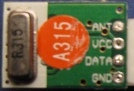
- The vcc pin is connected to the +terminal in the circuit.
- The data pin is connected to the HT12E(pin no-17) that is transmitted or we can say that encoded data.
- The next pin is shown in figure is GND that is connected to the ground terminal.
- now the last pin ANT this is connected to a small wire as an antenna.
 |
| HT12E encoder |
- pin (1 to 8) A0-A7 known as address bits so we do not need to consider them.
- pin no (9 and 18) are use to bias the IC as pin-18 as VCC and pin-9 as GND.
- pin - 17 is connected to the rf transmitter module Din.
- pin-16 and pin-15 are connected by an Osc resistor known as Roscc(1.1 Mohm)
- pin-14 is connected to ground to enable the transmitt.
- pin-13 to pin-10 are known as AD0 to AD3 those having the 4bit data which is required to transmitt.
 |
| CIRCUIT DIAGRAM OF REMOTE. |
 |
| actual remote |
RECEIVER BOX:The receiver box consist of the circuit of RF Receiver module , the decoder IC HT12D circuit, decision ciruit (Microcontroller 8051 circuit ) , relay and relay driver circuit (ULN 2003 IC circuit),
remote controller appliances
19:30